


48 PI-MTE System Manual Version 4.C
Binning also reduces readout time and the burden on computer memory, but at the
expense of resolution. Since shift register pixels typically hold only twice as much
charge as image pixels, the binning of large sections may result in saturation and
“blooming”, or spilling of charge back into the image area.
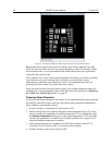
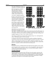
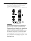
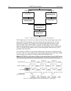
Figure 13 shows an example of 2 2 binning. Each pixel of the image displayed by the
software represents 4 pixels of the CCD array. Rectangular bins of any size are possible.
Figure 13. 2 × 2 Binning for Images
Software Binning
One limitation of hardware binning is that the shift register pixels and the output node are
typically only 2-3 times the size of imaging pixels. Consequently, if the total charge binned
together exceeds the capacity of the shift register or output node, the data will be lost.
This restriction strongly limits the number of pixels that may be binned in cases where there is
a small signal superimposed on a large background, such as signals with a large fluorescence.
Ideally, one would like to bin many pixels to increase the S/N ratio of the weak peaks but this
cannot be done because the fluorescence would quickly saturate the CCD.
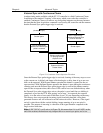
The solution is to perform the binning in software. Limited hardware binning may be used
when reading out the CCD. Additional binning is accomplished in software, producing a
result that represents many more photons than was possible using hardware binning.
Software averaging can improve the S/N ratio by as much as the square root of the
number of scans. Unfortunately, with a high number of scans, i.e., above 100, camera 1/f
noise may reduce the actual S/N ratio to slightly below this theoretical value. Also, if the
light source used is photon-flicker limited rather than photon shot-noise limited, this
theoretical signal improvement cannot be fully realized. Again, background subtraction
from the raw data is necessary.