


58 PI-MTE System Manual Version 4.C
TTL Control
Fully supported by WinView/WinSpec Version 2.6.x when the communication protocol
is TAXI (PCI). This feature is not supported when the protocol is USB 2.0.
Introduction
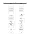
Princeton Instruments' WinView and WinSpec software packages incorporates WinX32
Automation, a programming language that can be used to automate performing a variety
of data acquisition and data processing functions, including use of the TTL In/Out
functions. WinX32 Automation can be implemented in programs written in Visual Basic
or Visual C++. Refer to the WinX32 documentation for more detailed information.
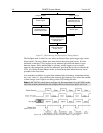
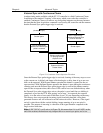
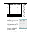
The TTL lines are made available through the TTL In/Out connector on the rear of the
ST-133 Controller. This connector provides 8 TTL lines in, 8 TTL lines out and an
input control line. Figure 22 illustrates the connector and Table 5 lists the signal/pin
assignments.
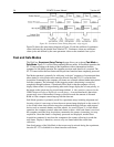
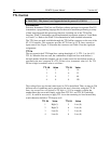
TTL In
The user controls the 8 TTL Input lines, setting them high (+5 V; TTL 1) or low (0 V;
TTL 0). When the lines are read, the combination of highs and lows read defines a
decimal number which the computer can use to make a decision and initiate actions as
specified in the user’s program. If a TTL IN line is low, its numeric value is 0. If a TTL
IN line is high, its numeric value is as follows.
TTL IN
Value
TTL IN
Value
1
1
5
16
2
2
6
32
3
4
7
64
4
8
8
128
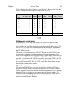
This coding allows any decimal value from 0 to 255 to be defined. Thus, as many as 256
different sets of conditions can be specified, at the user’s discretion, using the TTL IN
lines. Any unused lines will default to TTL high (+5 V). For example, to define the
number three, the user would simply set the lines TTL IN 1 and TTL IN 2 both high
(+5 V). It would be necessary to apply TTL low to the remaining six lines because they
would otherwise default to TTL high as well.
TTL IN
Value
TTL IN
Value
1
High (1)
5
Low (0)
2
High (2)
6
Low (0)
3
Low (0)
7
Low (0)
4
Low (0)
8
Low (0)