


Chapter 2 System Component Descriptions 15
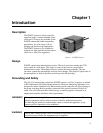
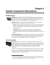
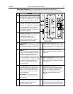
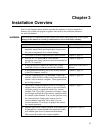
Rear Panel Features: The rear panel connector descriptions are keyed to the
accompanying figure. The Fuse/Voltage label will be above or below the Power Module.
#
Feature
120Vac
50-60Hz
FUSES: LEFT: RIGHT:
100 - 120V ~ 0.75A - T 2.50A - T
220 - 240 V ~ 0.30A - T 1.25 A- T
SHUTTER CONTROL
REMOTE
SETTING
TTL IN/OUT
AUX
VIDEO
TEMP
LOCK
EXT SYNC
SCAN
READY
ZERO
F
S
DETECTOR
TTL
IN/OUT
AUX
USB 2.0
SERIAL COM
USB 2.0TAXI
Interface Control Module
1
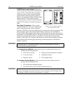
Temperature Lock LED: Indicates that
the temperature control loop has locked
and that the temperature of the CCD
array will be stable to within 0.05C.
2
Video/Aux Output: If labeled Video,
composite video output is provided at this
connector. The amplitude is 1 V pk-pk and
the source impedance is 75 . Note that
video output is not currently supported
under USB 2.0. If labeled Aux, this output
is reserved for future use.
3
External Sync Input: TTL input that has
a 10 k pullup resistor. Allows data
acquisition and readout to be
synchronized with external events.
Through software, positive or negative
(default) triggering can be selected.
4
Output: WinView/32 (ver. 2.4 and
higher) software selectable NOT SCAN or
SHUTTER signal. Default is SHUTTER.
10
Serial COM Connector: Provides two-way
serial communication between the controller
and the host computer. Uses TAXI protocol.
5
Output: Initially HIGH. After a
Start Acquisition command, this output
changes state on completion of the array
cleaning cycles that precede the first
exposure. Initially high, it goes low to
mark the beginning of the first exposure.
In free run operation it remains low until
the system is halted. If a specific number
of frames have been programmed, it
remains low until all have been taken,
then returns high.
11
Fan: Cools the controller electronics.
Runs continuously when the controller is
turned on.
12
Shutter Setting Selector: Sets the shutter
drive voltage. Dial is correctly set at the
factory for the camera’s internal shutter if
one is present.
6
Zero Adjustment: Bias potentiometers
control the offset values of the Fast (F) and
Slow (S) A/D converters. Preadjusted at
factory. For 2 MHz controllers, baseline
offset values are set at the factory and are
not user-changeable.
CAUTION: Do not adjust the offset
values to zero, or some low-level data
will be missed.
13
Remote Shutter Connector: Provides
shutter-drive pulses for an external shutter.
An ST-133 with the 70 V shutter option is
required for a camera with the 40 mm
shutter. A 70 V OPT label will be next to the
Remote connector when this option is
installed.
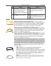
7
Detector Connector: Transmits control
information to the camera and receives
data back from the camera via the
Detector-Controller cable.
14
Power Module: Contains the power cord
socket and two fuses. Depending on the
ST-133 version, the power switch may be
located directly above the power module.