


Chapter 6 Advanced Topics 59
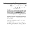
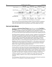
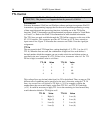
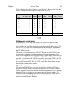
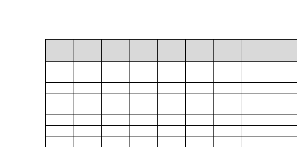
Table 4 illustrates this coding for decimal values 0 through 7. Obviously this table could
easily be extended to show the coding for values all the way to 255.
Decimal
Equiv.
TTL
IN/OUT 8
1= dec 128
TTL
IN/OUT 7
1=dec 64
TTL
IN/OUT 6
1=dec 32
TTL
IN/OUT 5
1=dec 16
TTL
IN/OUT 4
1=dec 8
TTL
IN/OUT 3
1=dec 4
TTL
IN/OUT 2
1=dec 2
TTL
IN/OUT 1
1=dec 1
0
0
0
0
0
0
0
0
0
1
0
0
0
0
0
0
0
1
2
0
0
0
0
0
0
1
0
3
0
0
0
0
0
0
1
1
4
0
0
0
0
0
1
0
0
5
0
0
0
0
0
1
0
1
6
0
0
0
0
0
1
1
0
7
0
0
0
0
0
1
1
1
Table 4. Bit Values with Decimal Equivalents:
1 = High,
0 = Low
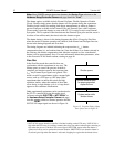
Buffered vs. Latched Inputs
In controlling the TTL IN lines, users also have the choice of two input-line states,
buffered or latched. In the buffered state, the line levels must remain at the intended
levels until they are read. With reference to the preceding example, the high level at TTL
IN 1 and TTL IN 2 would have to be maintained until the lines are read. In the latched
state, the applied levels continue to be available until read, even if they should change at
the TTL In/Out connector.
This control is accomplished using the EN/CLK TTL input (pin 6). If EN/CLK is open
or high, buffered operation is established and the levels reported to the macro will be
those in effect when the READ is made. With reference to our example, if pin 6 were left
unconnected or a TTL high applied, TTL IN 1 and TTL IN 2 would have to be held high
until read. If, on the other hand, EN/CLK were made to go low while TTL IN 1 and TTL
IN 2 were high, those values would be latched for as long as EN/CLK remained low. The
levels actually present at TTL IN 1 and TTL IN 2 could then change without changing
the value that would be read by software.
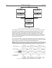
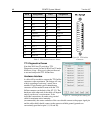
TTL Out
The state of the TTL OUT lines is set from WinView/32 (or WinSpec/32). Typically, a
program (for example, a macro) monitoring the experiment sets one or more of the TTL
Outputs. Apparatus external to the PI-MTE system interrogates the lines and, on detecting
the specified logic levels, takes the action appropriate to the detected condition. The
coding is the same as for the input lines. There are eight output lines, each of which can
be set low (0) or high (1). The combination of states defines a decimal number as
previously described for the TTL IN lines.