


2 - 42
2 MULTIPLE CPU SYSTEM
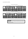
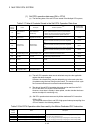
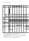
(1) Self CPU operation data area (0H to 1FFH)
(a) The following data of the self CPU are stored in the Multiple CPU system,
Table 2.1 Table of Contents Stored in the Self CPU Operation Data Area
Shared
memory
address
Name Description
Detailed explanation
(Note)
Corresponding
special resister
0H
Data available/not
available
"Data available/not
available" flag
This area is used to check whether data is stored or not in the
self CPU operation data area (1H to 1FH) of the self CPU.
• 0: Data is not stored in the self CPU operation data area.
• 1: Data is stored in the self CPU operation data area.
—
1H Diagnosis error Diagnosis error number
The error number of an error generated during diagnosis is
stored as a BIN code.
D9008
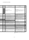
2H
The year and month when the error number was stored in
address 1H of shared CPU memory is stored in 2-digit BCD
code.
D9010
3H
The date and hour when the error number was stored in
address 1H of shared CPU memory is stored in 2-digit BCD
code.
D9011
4H
Diagnosis-error
occurrence time
Diagnosis-error
occurrence time
The minutes and seconds when the error number was stored in
address 1H of shared CPU memory is stored in 2-digit BCD
code.
D9012
5H Error-data category code Error-data category code
Category codes indicating the nature of the stored common
error data and individual error data are stored.
D9013
6H Error data Error data
Common data corresponding to the error number of an error
generated during diagnosis is stored.
D9014
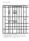
7H to 1CH Not used —
Not used
—
1DH Switch status CPU switch status
The switch status of the CPU is stored.
D9200
1EH LED status CPU-LED status
The bit pattern of the CPU LED is stored
D9201
1FH CPU operation status CPU operation status
The operation status of the CPU is stored.
D9015
(Note) : Refer to the corresponding special register for details.
(b) The self CPU operation data area is refreshed every time the applicable
register has been changed.
However, the refresh timing may be delayed by up to the main cycle time.
(It updates using idle time during motion control. The maximum main cycle
time: several milliseconds to several hundred milliseconds).
(c) The data of the self CPU operation data area can be read from the PLC
CPU of the other CPU by the FROM instruction.
However, since there is a delay in data update, use the data that has been
read as an object for monitoring only.
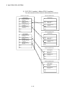
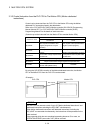
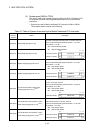
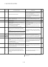
(d) Self CPU operation data area used by Motion dedicated PLC instruction
(30H to 33H)
The complete status of the to self CPU high speed interrupt accept flag from
CPUn is stored in the following address.
Table 2.2 Self CPU Operation data Area used by the Motion Dedicated PLC Instruction
Shared
memory
address
Name Description
30H(48) To self CPU high speed interrupt accept flag from CPU1
31H(49) To self CPU high speed interrupt accept flag from CPU2
32H(50) To self CPU high speed interrupt accept flag from CPU3
33H(51) To self CPU high speed interrupt accept flag from CPU4
This area is used to check whether to self CPU high speed interrupt accept flag
from CPUn can be accepted or not.
0: To self CPU high speed interrupt accept flag from CPUn accept usable.
1: To self CPU high speed interrupt accept flag from CPUn accept disable.