2 - 12
2 MULTIPLE CPU SYSTEM
1)
PLC CPU
Motion CPU
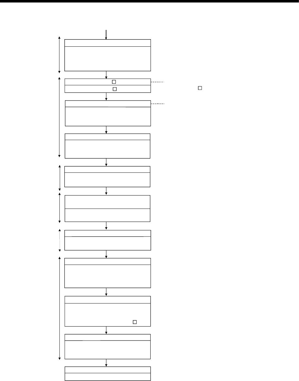
Write to the PLC CPU
Write the parameters and PLC programs
to the PLC CPU (CPU No.1).
Set the connect destinations of PLC CPU
(CPU No. 2 to 4), and write them.
SW6RN-GSV P start
Start the SW6RN-GSV P.
System settings and program, etc. create
Create the system settings, servo data
and Motion SFC program (SV13/SV22)/
Motion program (SV43).
• Refer to Section 3.1 for system settings.
• Refer to the Programming Manual of each
operating system software for details of program.
Write to the Motion CPU
Write the system settings, servo data
and Motion SFC program (SV13/SV22)/
Motion program (SV43).
PLC CPU
PLC CPU (CPU No.1) reset
Set the RESET/L.CLR switch to RESET
position.
PLC CPU
Motion CPU
Change back the RESET/L.CLR switch
to OFF position and release the reset.
Set RUN/STOP switch for all CPUs to
RUN position.
Release PLC CPU (CPU No.1) reset
Set the RUN/STOP switch for each CPU
(CPU No.1 to 4) to RUN position.
PLC CPU
Check of state for all CPUs
Check whether all CPUs in the Multiple
CPU system become RUN state/error by
reset release of the PLC CPU (CPU
No.1).
PLC CPU
Motion CPU
Check and correct the error details
Each CPU debug
If an error has occurred, check and
correct the error details using the PC
diagnostic function of GX developer and
error list monitor of SW6RN-GSV P.
Execute the individual debug of PLC
CPU/Motion CPU (CPU No. 1 to 4) and
debug as the Multiple CPU system.
Actual operation
• Refer to the help for operation of
SW6RN-GSV P.
Actual operation
Check in the automatic operation.
(Note) : Installation of the operating system software is required to the Motion CPU module before start of
the Multiple CPU system.
Refer to Chapter 5 of the "Q173HCPU/Q172HCPU User's Manual" for installation of the Motion
CPU operating system software.


