


4 - 5
4 AUXILIARY AND APPLIED FUNCTIONS
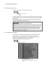
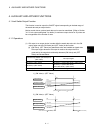
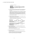
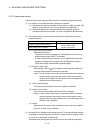
(2) Watch data
(a) This data is used to perform the limit switch output function. This data is
comparison data to output the ON/OFF signal. The output device is
ON/OFF-controlled according to the ON region setting.
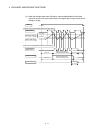
(b) As the watch data, motion control data or optional word device data can be
used.
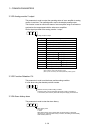
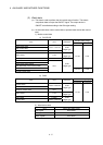
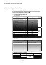
1) Motion control data
a) SV13/SV22
Axis No. setting range
Item Unit Data type
Q173HCPU Q172HCPU
Feed current value
Real current value
Position command
Deviation counter value PLS
32-bit
integer type
Motor current 0.1%
16-bit
integer type
Motor speed 0.1r/min
Cam shaft within-one-revolution current value
Feed current value (Virtual)
After-differential current value (Virtual)
1 to 32 1 to 8
After-differential encoder current value
Encoder current value
PLS
32-bit
integer type
1 to 12 1 to 8
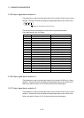
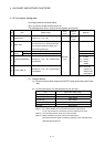
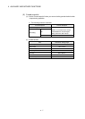
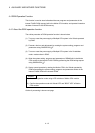
b) SV43
Axis No. setting range
Item Unit Data type
Q173HCPU Q172HCPU
Machine value
Real machine value
Position command
Deviation counter value PLS
32-bit
integer type
Motor current 0.1%
16-bit
integer type
Motor speed 0.1r/min
Current value Position command
32-bit
integer type
1 to 32 1 to 8
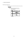
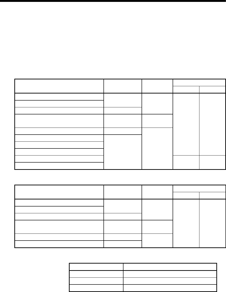
2) Word device data
Item Device No. setting range
Data register D0 to D8191
Link register W0 to W1FFF
Motion register #0 to #8191