


2 - 16
2 MULTIPLE CPU SYSTEM
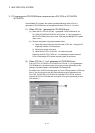
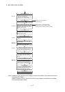
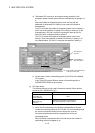
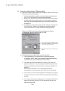
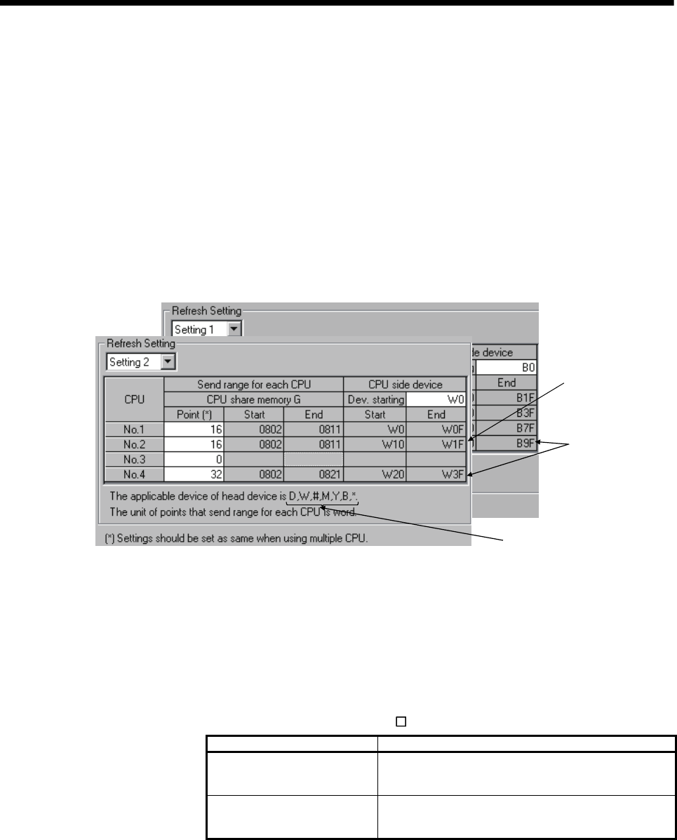
4) The shared CPU memory to be occupied during execution of the
automatic refresh function covers all areas corresponding to settings 1 to
4.
When the number of transmitting points is set, the first and last
addresses of the shared CPU memory to be used are indicated in
hexadecimals.
The CPU for which the number of transmitting points is set in settings 1
and 2 use the last address of shared CPU memory in setting 2. (In the
example below, CPU No.1 and No.2 are using the area up to 811H,
while CPU No.4 is using the area up to 821H.)
The CPU for which the number of transmitting points is set only in
setting 1 use the last address of shared CPU memory in setting 1. (In
the example below, CPU No.3 is using the last address in setting 1).
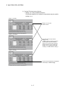
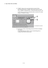
• Send range for
CPU No.1
• Last address of
CPU-side device
• Last address of the shared CPU
memor
y
for each CPU
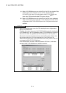
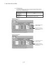
5) Set the same number of transmitting points for all CPUs in the Multiple
CPU system.
If any of the CPUs has a different number of transmitting points, a
PARAMETER ERROR will be occurred.
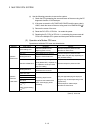
(c) CPU-side device
The following devices can be used for automatic refresh. (Other devices
cannot be set in SW6RN-GSV
P.)
Settable device Restriction
Data resister (D)
Link resister (W)
Motion resister (#)
None
Link relay (B)
Internal relay (M)
Output (Y)
• Specify 0 or a multiple of 16 as the first No..
• One transmitting point occupies 16 points.
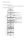
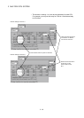
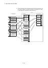
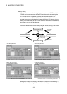
1) As for the CPU-side devices, the devices corresponding to the total
number of transmitting points set for CPU No.1 to 4 in one setting range
are used in succession starting from the device No. to be set.
Set a device number that ensures enough devices for the set
transmitting points.
When bit device is specified for the CPU-side device, the number of
transmitting points is multiplied by 16.