


3 - 23
3 COMMON PARAMETERS
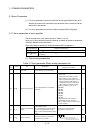
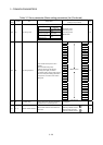
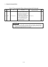
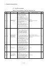
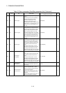
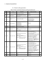
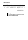
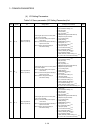
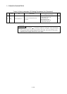
Table 3.2 Servo parameter (Gain/filter parameters) list (Continued)
LED
display
Symbol Item Setting details
Setting value/setting range
(Setting by setup software)
Section
PB07 PG1 Model loop gain
• Set the response gain up to the target
position.
• Increase the gain to improve trackability in
response to the position command.
• When the auto tuning mode 1 or 2 is
selected, the result of auto tuning is
automatically used. When "PA08 Auto tuning
mode" is set to "1: Auto tuning mode 1" or "3:
Manual mode", the manual setting can be
executed.
1 to 2000[rad/s] —
PB08 PG2 Position loop gain
• Set the gain of the position loop.
• Set this parameter to increase the position
response to level load disturbance. Higher
setting increases the response level but is
liable to generate vibration and/or noise.
• When the auto tuning mode 1 or 2, manual
mode and interpolation mode is selected, the
result of auto tuning is automatically used.
When "PA08 Auto tuning mode" is set to "3:
Manual mode", the manual setting can be
executed.
1 to 1000[rad/s] —
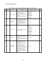
PB09 VG2 Speed loop gain
• Set the gain of the speed loop.
• Set this parameter when vibration occurs on
machines of low rigidity or large backlash.
Higher setting increases the response level
but is liable to generate vibration and/or
noise.
• When the auto tuning mode 1 or 2 and
interpolation mode is selected, the result of
auto tuning is automatically used. When
"PA08 Auto tuning mode" is set to "3: Manual
mode", the manual setting can be executed.
20 to 50000[rad/s] —
PB10 VIC
Speed integral
compensation
• Set the integral time constant of the speed
loop.
• Lower setting increases the response level
but is liable to generate vibration and/or
noise.
• When the auto tuning mode 1 or 2 and
interpolation mode is selected, the result of
auto tuning is automatically used. When
"PA08 Auto tuning mode" is set to "3: Manual
mode", the manual setting can be executed.
0.1 to 1000.0[ms] —
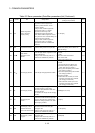
PB11 VDC
Speed differential
compensation
• Set the differential compensation.
• It becomes valid when PID is set in the PI-
PID switching.
0 to 1000 —
PB13 NH1
Machine resonance
suppression filter 1
• Set the notch frequency of the machine
resonance suppression filter 1. (Set the
frequency to match the response frequency
of the mechanical system.)
• Setting of "PB01 Adaptive tuning mode" to "1:
Filter tuning mode" automatically sets this
parameter.
• Setting of "PB01 Adaptive tuning mode" to "0:
Filter OFF" invalidates this parameter.
100 to 4500[Hz] —