


87
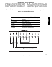
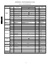
APPENDIX B - VFD INFORMATION (CONT)
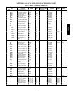
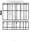
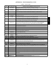
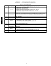
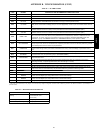
Table 41 — FAULT CODES
FAULT
CODE
FAULT NAME IN PANEL DESCRIPTION AND RECOMMENDED CORRECTIVE ACTION
1
OVERCURRENT
Output current is excessive. Check for excessive motor load, insufficient acceleration time (parameters 2202
ACCELER TIME 1, default 30 seconds), or faulty motor, motor cables or connections.
2
DC OVERVOLT
Intermediate circuit DC voltage is excessive. Check for static or transient over voltages in the input power supply,
insufficient deceleration time (parameters 2203 DECELER TIME 1, default 30 seconds), or undersized brake chopper
(if present).
3
DEV OVERTEMP
Drive heat sink is overheated. Temperature is at or above 115_C (239_F). Check for fan failure, obstructions in the air
flow,dirtordustcoatingontheheatsink,excessiveambienttemperature,orexcessivemotorload.
4 SHORT CIRC Fault current. Check for short---circuit in the motor cable(s) or motor or supply disturbances.
5 OVERLOAD Inverter overload condition. The drive output current exceeds the ratings.
6
DC OVERVOLT
Intermediate circuit DC voltage is not sufficient. Check for missing phase in the input power supply, blown fuse, or
under voltage on main circuit.
7
Al1 LOSS
Analog input 1 loss. Analog input value is less than AI1 FLT LIMIT (3021). Check source and connection for analog
input and parameter settings for AI1 FLT LIMIT (3021) and 3001 AI<MIN FUNCTION.
8
Al2 LOSS
Analog input 2 loss. Analog input value is less than AI2 FLT LIMIT (3022). Check source and connection for analog
input and parameter settings for AI2 FLT LIMIT (3022) and 3001 AI<MIN FUNCTION.
9
MOT OVERTEMP
Motor is too hot, as estimated by the drive. Check for overloaded motor. Adjust the parameters used for the estimate
(3005 through 3009). Check the temperature sensors and Group 35 parameters.
10
PANEL LOSS
Panel communication is lost and either drive is in local control mode (the control panel displays LOC), or drive is in
remote control mode (REM) and is parameterized to accept start/stop, direction or reference from the control panel.
To correct check the communication lines and connections. Check parameter 3002 PANEL COMM ERROR,
parameters in Group 10: Command Inputs andGroup 11:Reference Select (if drive operation is REM).
11 ID RUN FAIL The motor ID run was not completed successfully. Check motor connections.
12
MOTOR STALL
Motor or process stall. Motor is operating in the stall region. Check for excessive load or insufficient motor power.
Check parameters 3010 through 3012.
13 RESERVED Not used.
14 EXT FAULT 1 Digital input defined to report first external fault is active. See parameter 3003 EXTERNAL FAULT 1.
15 EXT FAULT 2 Digital input defined to report second external fault is active. See parameter 3004 EXTERNAL FAULT 2.
16
EARTH FAULT
The load on the input power system is out of balance. Check for faults in the motor or motor cable. Verify that motor
cable does not exceed maximum specified length.
17
UNDERLOAD
Motor load is lower than expected. Check for disconnected load. Check parameters 3013 UNDERLOAD FUNCTION
through 3015 UNDERLOAD CURVE.
18 THERM FAIL Internal fault. The thermistor measuring the internal temperature of the drive is open or shorted. Contact Carrier.
19
OPEX LINK
Internal fault. A communication---related problem has been detected between the OMIO and OINT boards. Contact
Carrier.
20 OPEX PWR Internal fault. Low voltage condition detected on the OINT board. Contact Carrier.
21 CURR MEAS Internal fault. Current measurement is out of range. Contact Carrier.
22 SUPPLY PHASE Ripple voltage in the DC link is too high. Check for missing main phase or blown fuse.
23 RESERVED Not used.
24
OVERSPEED
Motor speed is greater than 120% of the larger (in magnitude) of 2001 MINIMUM SPEED or 2002 MAXIMUM SPEED
parameters. Check parameter settings for 2001 and 2002. Check adequacy of motor braking torque. Check
applicability of torque control. Check brake chopper and resistor.
25 RESERVED Not used.
26 DRIVE ID Internal fault. Configuration block drive ID is not valid.
27 CONFIG FILE Internal configuration file has an error. Contact Carrier.
28
SERIAL 1 ERR
Field bus communication has timed out. Check fault setup (3018 COMM FAULT FUNC and 3019 COMM FAULT
TIME). Check communication settings (Group 51 or 53 as appropriate). Check for poor connections and/or noise on
line.
29 EFB CON FILE Error in reading the configuration file for the field bus adapter.
30 FORCE TRIP Faulttripforcedbythefieldbus.Seethefieldbusreferenceliterature.
31 EFB 1 Fault code reserved for the EFB protocol application. The meaning is protocol dependent.
32 EFB 2 Fault code reserved for the EFB protocol application. The meaning is protocol dependent.
33 EFB 3 Fault code reserved for the EFB protocol application. The meaning is protocol dependent.
34
MOTOR PHASE
Fault in the motor circuit. One of the motor phases is lost. Check for motor fault, motor cable fault, thermal relay fault ,
or internal fault.
35 OUTP WIRING Error in power wiring suspected. Check that input power wired to drive output. Check for ground faults.
101---105 SYSTEM ERROR Error internal to the drive. Contact Carrier and report the error number.
201---206 SYSTEM ERROR Error internal to the drive. Contact Carrier and report the error number.
48/50PD