


12
Password Enable (PROT)
This variable enables or disables the use of a password. The
password is used to restrict use of the control to change
configurations.
Servic e Password (PSWD)
This variable is the 4-digit numeric password that is required if
enabled.
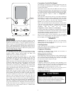
Test Display LEDs (TEST)
This is used to test the operation of the ComfortLinkt display.
Modes
The ComfortLink controls operate under a hierarchy of command
structure as defined by four main elements: the System Mode, the
HVAC Mode, the Occupied status, and the Unit Control Type.
The System Mode is the top level that defines three main states of
the control system: Disabled, Enabled, or Test.
The HVAC Mode is the next level that defines four main states of
functional operation: Disabled, Fan Only, Cool, and Heat.
The Occupied status affects set points for cooling and heating in
Space Sensor control mode and operation of the economizer for
indoor air quality ventilation and free cooling.
The general operating mode of the control and the status of some
related operation lockouts are located on the display at two
locations: Run Status→ MODE and Operating Modes→ MODE.
System Mode (SYS)
In Run Status and Operating Modes, the current system mode is
displayed with expandable text. This is an overall state of the unit.
Three states are: Unit Operation Disabled, Unit Operation Enabled,
or Service Test Enabled.
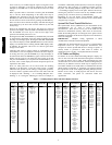
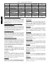
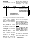
HVAC Mode (HVAC)
In Run Status and Operating Modes, the current allowed HVAC
mode is displayed with expandable text. This is the mode the unit
decides to run in based on its inputs. There are four main HVAC
modes; cooling has three different expanded texts. These modes
are shown below.
HVAC
Mode
Expanded Text Brief Description
Disabled HVAC Operation
Disabled
Unit is in test mode or System mode is
disabled
Fan Only Ventilation
(fan--only)
Fan may run for ventilation
Cooling
Cooling Mechanical coo ling
Free Cooling Only economizer used for cooling
Unoccu pied Free
Cooling
Only economizer use for cooling
(occupied cooling set poin t active)
Heating Heating Heating mode
Remote HVAC Mode Disabled (HV.DN)
Allow disabling of HVAC mode. This is only available on a
network connection.
Cool Setpoint in Effect (EFF.C)
This shows the actual setpoint that is being used for control during
cooling mode.
Heat Setpoint in Effect (EFF.H)
This shows the actual setpoint that is being used for control during
heating mode.
Currently Occupied (OCC)
Displays the current state of assumed space occupancy based on
unit configuration and inputs.
Timed Override in Effect (T.OVR)
Displays if the state of occupancy is currently occupied due to an
override.
Linkage Active (LINK)
Displays if Linkage communication is established between the unit
and a Linkage source.
IMPORTANT: The 48/50PD unit only supports the Gen III
TEMP Monitor Thermostat.
Demand Limit in Effect (D.LMT)
Displays if a demand limit has been placed on the unit’s capacity .
Circuit OAT Lockout (C.LOC)
Displays if one or more refrigerant circuits operation is prevented
due to outdoor temperature limit lockout.
Heat OAT Lockout (H.LOC)
Displays if heating operation is prevented due to outdoor
temperature limit lockout.
Econo Cool OAT Lockout (E.LOC)
Displays if economizer operation for cooling is prevented due to
outdoor temperature limit lockout.
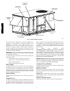
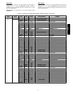
Unit Configuration
Many configurations that indicate what factory options and/or field
accessories are installed and other common operation variables are
included in Unit Configuration (Configuration→UNIT).
Configuration will be done at the factory for any factory-installed
option (FIOP).
Start--Up Delay (S.DLY)
This configuration sets the control start-up delay after the power is
interrupted. This can be used to stagger the start-up of multiple
units.
FanOnWhenOccupied(OC. FN)
A YES value will operate the indoor fan whenever the unit is in the
Occupied mode. A NO value will operate the indoor fan only when
heating or cooling is necessary. The factory default value is YES.
Shut Down on IDF Failure (IDF.F)
This configuration applies only if a fan switch is installed and
configured. A YES value will enable diagnostic Alert T409 to shut
down the unit when incorrect fan status is sensed. A NO value will
still permit Alert T409 but will not cause unit shutdown. The
factory default value is YES.
Supply Fan Maximum Spe ed (FS.MX)
This configuration sets the limit for the highest speed the fan can
run out of 100%. This max speed limit applies to the unit at all
times except for fan test.
Supply Fan Minimum Speed (FS.MN)
This configuration sets the limit for the lowest speed the fan can
run out of 100%. This minimum speed limit applies to the unit
during cooling mode and cooling test.
Vent Mode Fan Speed (FS.VM)
This configuration sets the speed the fan will run during the
ventilation mode. The fan speed does not vary during ventilation
so it will remain at this speed throughout vent mode.
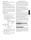
Fan Status Switch (FN.SW)
This configuration identifies i f a fan status switch is installed, and
what status (normally open, normally closed) the input is when the
indoor fan is OFF.
Filter St atus Switch (FL.SW)
This configuration identifies if a filter status switch is installed, and
what status (normally open, normally closed) the input is when the
filter is CLEAN.
Fire Shutdown Switch (FS.SW)
This configuration identifies if a fire shutdown switch is installed,
and what status (normally open, normally closed) the input is when
the fire or smoke alarm is OFF (no alarm).
Remote Occupancy Switch (RM.SW)
This configuration identifies if a remote occupancy switch is
installed, and what status (normally open, normally closed) the
input is when UNOCCUPIED.
48/50PD