


17
exceed Econ Min at Max Fan Speed
(Configuration→ECON→MP.MX) or IAQ Override Position
(Configuration→AIR.Q→OVR.P) to provide economizer
cooling.
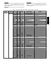
IA.CF = 3 (Control Minimum Position)
When IA.CF = 3, an external 4 to 20 mA source is used to set the
minimum position. The 4mA signal corresponds to 0% and the 20
mA signal corresponds to 100%. In this mode, configuration such
as Econ Min at Max Fan Speed
(Configuration→ECON→MP.MX), Econo Min IAQ Position
(Configuration→AIR.Q→AQ.MN) and the economizer minimum
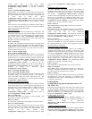
position and DCV minimum position curves in figure 3 are not
used.
If the indoor fan is not operating, the economizer position will be
zero. The damper position may exceed the economizer minimum
position to provide economizer cooling.
IAQ (Switch
Input)
Indoor air quality can also be measured using a switch input. For
the purpose of specifying the type of switch input, low CO2 lev els
are considered normal. The IAQ switch input is defined by the
IAQ Switch Input Config (Configuration→AIR.Q→II.CF).
Enthalpy and IAQ are controlled by the same switch input and
therefore cannot be used simultaneously.
II.CF = 0 (NO IAQ)
The II.CF = 0, configuration signifies that there is no IAQ switch
input. The damper will operate at the Econ Min at Max Fan Speed
(Configuration→ECON→MP.MX) and corresponding damper
position curve based on indoor fan speed when the space is
occupied and the indoor fan is on.
II.CF = 1 (DCV Normally Open)
II.CF = 2 (DCV Normally Closed)
The Demand Control Ventilation (DCV) allows the economizer
minimum position to be decreased when there is no IAQ problem.
If IAQ is low, the economizer minimum position is Econo Min
IAQ Position (Configuration→AIR.Q→AQ.MN) when the indoor
fan is operating at Supply Fan Maximum Speed
(Configuration→UNIT→FS.MX). If IAQ is high, the
economizer minimum position is Econ Min at Max Fan Speed
(Configuration→ECON→MP.MX) when the indoor fan is
operating at Supply Fan Maximum Speed
(Configuration→UNIT→FS.MX).
II.CF = 3 (Override Normally Open)
II.CF = 4 (Override Normally Closed)
The damper override function permits absolute positioning of the
economizer damper for ventilation purposes. The override is
active when IAQ is high and inactive when IAQ is low. The
override position is configured by the IAQ Override Position
(Configuration→AIR.Q→OVR.P).
Outdoor Air Quality (Analog
Input)
The ComfortLink TM control is configured for outdoor air quality
sensors which provide a 4 to 20 mA signal corresponding to 0 to
2000 ppm CO2. If a field supplied sensor has a different range, the
ppm display range must be reconfigured by entering new values
for the OAQ Sensor Value at 4mA
(Configuration→AIR.Q→O.4M) and OAQ Sensor Value at
20mA (Configuration→AIR.Q→O.20M).
OA.CF = 0 (NO OAQ)
This signifies that there is no outdoor air sensor installed. The
default value of OAQ is 400 ppm CO2.
OA.CF = 1 (DCV)
The outdoor air quality sensor analog input is the value of OAQ.
OA.CF = 2 (OAQ Lockout)
The outdoor air quality analog input is only used to lock out the
outdoor ventilation. The economizer commanded position is set to
0% when the CO2 ppm exceeds the OAQ lockout value
configured for the OAQ Lockout Limit
(Configuration→AIR.Q→AQ.L). The default value for OAQ
Lockout Limit (Configuration→AIR.Q→OAQ.L) is 600 ppm
CO2.
Fan Enable (Analog IAQ
Sensor)
The DCV algorithm will operate whenever the building is
occupied and the indoor fan is operating or whenever the IAQ
algorithm has caused the indoor fan to operate. The IAQ Analog
Fan Config (Configuration→AIR.Q→IA.FN) determines
whether or not the IAQ algorithm can turn on the indoor fan. If the
indoor fan is not operating, the economizer position will be zero.
The damper position may exceed Econ Min at Max Fan Speed
(Configuration→ECON→MP.MX) and corresponding damper
position curve to provide economizer cooling.
IA.FN = 0 (Never)
When IA.FN =0, the IAQ algorithm can never turn on the fan.
IA.FN = 1 (Occupied)
When IA.FN =1, the IAQ algorithm will turn on the indoor fan
whenever the building is occupied and IAQ/OAQ differential is
greater than the Fan On AQ Differential
(Configuration→AIR.Q→DF.ON). The indoor fan will turn off
when the IAQ/OAQ differential is less than the Fan Off AQ
Differential (Configuration→AIR.Q→DF.OF).
IA.FN = 2 (Always)
The indoor fan operation for IA.FN =2,isthesameasthe
operation when IA.FN =1, except the algorithm is not limited to
the occupied periods only. The fan can be triggered on when the
space is occupied or unoccupied.
Fan Enable (Analog Switch
Input)
The DCV algorithm will operate whenever the building is
occupied and the indoor fan is operating or whenever the IAQ
algorithm has caused the indoor fan to operate. The IAQ Switch
Fan Config (Configuration→AIR.Q→II.FN) determines whether
or not the IAQ algorithm can turn on the indoor fan. If the indoor
fan is not operating, the economizer position will be zero. The
damper position may exceed Econ M in at Max Fan Speed
(Configuration→ECON→MP.MX) and corresponding damper
position curve to provide economizer cooling.
II.FN = 0 (Never)
When II.FN =0, the IAQ algorithm can never turn on the fan.
II.FN = 1 (Occupied)
When II.FN =1, the IAQ algorithm will turn on the indoor fan
whenever the building is occupied and IAQ is high. The indoor
fan will turn off when the IAQ returns to normal.
II.FN = 2 (Always)
The indoor fan operation for II.FN =2, is the same as the operation
when IA.FN =1, except the algorithm is not limited to the
occupied periods only. The fan can be triggered on when the space
is occupied or unoccupied.
Cooling Modes
Cooling Mode Using Space Temperature Sensor T55,
T56, T58 or T59
In cooling mode the PD control will maintain the Occupied Cool
Set Point (Setpoint→OCSP) or the Unoccupied Cool Set Point
(Setpoints→UCSP) by modulating the indoor fan speed to supply
more or less airflow to the conditioned space at the Supply Air
Temperature (Temperatures→AIR.T→SAT).
Cooling Supply Air Set
Point
The Cool Supply Air Set Point (Setpoint→SASP)can be
configured between 45F and 75F. The compressor modulates to
maintain a Supply Air Temperature
(Temperatures→AIR.T→SAT)at the Cool Supply Air Set Point
(Setpoint→SASP).
Cooling Speed Demand W
indow
When the temperature in the conditioned space is higher than the
Occupied Cool Set Point (Setpoints→OCSP) plus the Fan Speed
Control Demand (Configuration→COOL?FS.CD) configuration
48/50PD