


4
down arrow keys to scroll through the top-level categories. These
are listed in Appendix A and will be indicated on the Scrolling
Marquee by the LED next to each mode listed on the face of the
display.
When a specific mode or sub-mode is located, push the ENTER
key to enter the mode. Depending on the mode, there may be
additional tiers. Continue to use the up and down keys and the
ENTER keys until the desired display item is found. At any time,
the user can move back a mode level by pressing the ESCAPE key.
Once an item has been selected the display will flash showing the
item, followed by the item value and then followed by the item
units (if any).
Items in the Configuration and Service Test modes are password
protected. The display will flash PASS and WORD when required.
Use the ENTER and arrow keys to enter the four digits of the
password. The default password is 1111.
Pressing the ESCAPE and ENTER keys simultaneously will scroll
an expanded text description across the display indicating the full
meaning of each display point. Pressing the ESCAPE and ENTER
keys when the display is blank (MODE LED level) will return the
display to its default menu of rotating AUTO VIEW display items.
In addition, the password will need to be entered again before
changes can be made.
Changing item values or testing outputs is accomplished in the
same manner. Locate and display the desired item. If the display is
in rotating auto-view, press the ENTER key to stop the display at
the desired item. Press the ENTER key again so that the item value
flashes. Use the arrow keys to change the value of state of an item
and press the ENTER key to accept it. Press the ESCAPE key and
the item, value or units display will resume. Repeat the process as
required for other items.
There are some points that can be forced from the Scrolling
Marquee or the Navigator. If the user needs to force a variable,
follow the same process as when editing a configuration parameter .
A forced variable, regardless where the force has come from will
be displayed with a blinking “.” on a Scrolling Marquee and a
blinking “f” on a Navigator following its value. For example, if
economizer commanded position (EC.CP) is forced, the Navigator
display shows “80f”, where the “f” is blinking to signify a force on
the point. The Sc rolling Marquee display shows “80.” Where the
“.” is blinking to signify a force on the point. Remove the force by
selecting the point that is forced with the key ENTER and then
pressing the up and down arrow keys simultaneously.
Depending on the unit model, factory-installed options and
field-installed accessories, some of the items in the various Mode
categories may not apply.
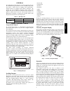
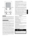
System Pilott a nd Touch Pilot Devices
The System Pilot device (33PILOT--01) and Touch Pilot device
(33CNTPILOT) can be used as CCN communication
user--interfaces. These devices can be put on the CCN bus and
addressed to communicate with any other device on the network.
Unlike the Scrolling Marquee and Navigator, these pilots read the
48/50PD’s CCN tables and the units CCN points can be monitored,
forced, or configured.
IMPORTANT: Multiple zoning application is NOT
recommended at this time with the PD products.
Additionally, the System Pilot device can serve as a wall-- mounted
temperature sensor for space temperature measurement. The
occupant can use the System Pilot device to change set points. A
security feature is provided to limit access of features for
unauthorized users. See Fig. 3 for System Pilot device details.
CCN Tables and Display
In addition to the unit--mounted Scrolling Marquee display , the
user can also access the same information through the CCN tables
by using the Service tool or other CCN programs/devices. The
variable names used for the CCN tables and the Scrolling Marquee
menus may be different and more items may be displayed in the
CCN tables. Details on the CCN tables are i ncluded w ith the local
display menus in Appendix A. Appendix A is structured towards
the organization of the local display (Scrolling Marquee) menus.
Because of the variety of CCN programs and devices, the CCN
tables, sub --tables, and points are referenced within that
organization.
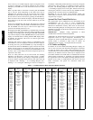
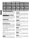
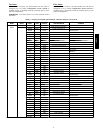
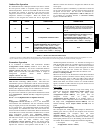
Table 2 — Scrolling Marquee Mode and Menu Display Structur e
RUN
STATUS
SERVICE
TEST
TEMPERATURES PRESSURES SETPOINTS INPUTS OUTPUTS CONFIGURATION
TIME
CLOCK
OPERATIN
G
MODES
ALARMS
Auto View
of
Run Status
(VIEW)
↓
Software
Version
Numbers
(VERS)
↓
Control
Modes
(MODE)
↓
Cooling
Status
(COOL)
↓
Heating
Status
(HEAT)
↓
Economizer
Status
(ECON)
↓
Component
Run Hours
(HRS)
↓
Component
Starts
(STRT)
Service Test
Mode
(TEST)
↓
Test Independent
Outputs
(INDP)
↓
Test Fans
(FANS)
↓
Test Cooling
(COOL)
↓
Test Heating
(HEAT)
Air
Temperatures
(AIR.T)
↓
Refrigerant
Temperatures
(REF.T)
General
Inputs
(GEN.I)
↓
Current
Sensor Inputs
(CS.IN)
↓
Air Quality
Inputs
(AIR.Q)
Fan
Outputs
(FANS)
↓
Cool
Outputs
(COOL)
↓
Heat
Outputs
(HEAT)
↓
Economize
r
Outputs
(ECON)
↓
Alarm
Relay
(ALRM)
Display
Configuration
(DISP)
↓
Unit
Configuration
(UNIT)
↓
Cooling
Configuration
(COOL)
↓
Heating
Configuration
(HEAT)
↓
Economizer
Configuration
(ECON)
↓
Air Quality
Cfg.
(AIR.Q)
↓
Alarm Relay
Config.
(ALM.O)
↓
PID
Configuration
(PID)
↓
Sensor
Calibration
(TRIM)
↓
CCN
Configuration
(CCN)
Time of Day
(TIME)
↓
Month, Date
Day and
Year
(DATE)
↓
Daylight
Savings
Time
(DST)
↓
Local Time
Schedule
(SCH.L)
↓
Local
Holiday
Schedules
(HOL.L)
Control
Modes
(MODE)
↓
Cool Mode
Diagnostic
(COOL)
↓
Heat Mode
Diagnostic
(HEAT)
↓
Economizer
Diagnostic
(ECON)
↓
Demand
Listing
(DMD.L)
Reset All
Current
Alarms
(R.CURR)
↓
Reset
Alarm
History
(R.HIST)
↓
Currently
Active
Alarms
(CURR)
↓
Alarm
HIstory
(HIST)
48/50PD