


25
AUX1 is not blinking, ch eck the DIP switch positions on the
board. If the red LEDs are not blinking in unison, verify that
correct power is being supplied to all modules. A blinking red
LED at the rate of once per second means that software is not
loaded on the board. Also, be sure that the board is supplied with
the current software. If necessary, reload current software. A board
LED that is lit continuously should be replaced.
Green LED
The MBB, ECB and AUX1 each have one green LED. The Local
Equipment Network (LEN) LED should always be blinking
whenever power is on. If LEN LED is not blinking, check LEN
connections for potential communication errors (MBB J3, J4, and
J5). Communication between modules is accomplished by a 3-wire
sensor bus. These 3 wires run in parallel from module to module.
The J4 connector on the MBB also provides both power and
communication directly to the Scrolling Marquee display . The J5
connector on the MBB provides a LEN interface at the field
connection terminal (TB).
Yellow LED
The MBB has one yellow LED which is used to indicate CCN
communication activity. The Carrier Comfort Network® (CCN)
LED will blink during times of network communication.
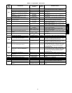
Communication Failures
If the Scrolling Marquee or Navigator display Communication
Failure or the green or yellow LED’s do not flash on the boards
then the problem could be the communication chip on one of the
contro l board s (MBB, ECB or AUX1 ). Use an ohm meter to
measure the resistance on the communication pins of the boards to
determine if the board is bad. If the reading is less than half the
value indicated in Table 7, then the board needs to be replaced.
Table 7 — LEN and CCN Communica tion Resistances
Device
Board Serial
Number
(LEN) Resistance between Pins/
Connector
(CCN) Resistance between Pins/
Connector
Pins 1 to 3 Pins 1 to 2 Pins 2 to 3 Pins 5 to 7 Pins 5 to 6 Pins 6 to 7
MBB
Prior to 4702N
15K Ω
J3, J4, & J5
7.5K Ω
J3, J4, & J5
7.5K Ω
J3, J4, & J5
15K Ω
J5
7.5K Ω
J5
7.5K Ω
J5
Starting 4702N
18.9K Ω
J3, J4, & J5
9.9K Ω
J3, J4, & J5
9.9K Ω
J3, J4, & J5
18.9K Ω
J5
9.9K Ω
J5
9.9K Ω
J5
ECB
Prior to 0803N
5.9K Ω
J2
5.2K Ω
J2
5K Ω
J2
--- --- ---
Starting 0803N
18.9K Ω
J2
9.9K Ω
J2
9.9K Ω
J2
--- --- ---
AUX1 ---
29K Ω
J9
16K Ω
J9
13.5K Ω
J9
--- --- ---
IMPORTANT: The resistive values should be read when the board is powered off and the unit is locked out.
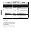
Alarms and Alerts
Viewing and Clearing Unit Alarms
Presence of active alarms will be indicated on the Scrolling
Marquee display by the Alarm Status light turning on and by the
number of active alarms being displayed in the automatic View of
Run Status. Presence of active alarms may also be signaled on the
Alarm Output terminals. Each alarm may also be broadcast on the
CCN network. Active alarms and past alarm history can be
reviewed and cleared via the local display or a CCN device. The
following menu locations are used for the local display:
Alarms→R.CURR (Reset All Current Alarms)
Change to YES to reset all active alarms. Turning unit power off
will also reset all current alarms.
Alarms→R.HIST (Reset Alarm History)
Change to YES to reset the alarm history. Turning unit power off
will not reset the alarm history .
Alarms→CURR (Currently Active Alarms)
Use the ENTER key, then scroll through any alarm numbers using
the up and down arrow keys. Alarms are displayed in numerical
order.
Alarms→HIST (Alarm History)
Use the ENTER key, then scroll through any alarm numbers using
the up and down arrow keys. Up to 20 alarms are displayed in
order of occurrence, with time and date.
The description for an alarm can be viewed on the Scrolling
Marquee display by pressing ESCAPE and ENTER keys
simultaneously while displaying the alarm code number. Be sure to
expand description for each code, because in some cases there are
different possible descriptions and causes for the same code
number.
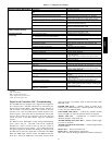
Diagnostic Alarm Codes and Possible Causes
Alert Code T051
There are 5 different texts for this alert code. There are three
different alerts, two of which have corresponding test mode alerts
indicated with “Service Test” in the expanded text. Pressing enter
and esc on the marquee or navigator to expand the T051 alert will
show you one of the below alerts. Make sure the expanded text is
read correctly before troubleshooting.
S Digital Compressor Control Board Alarm
This alert occurs when the Digital Scroll Controller (DSC)
energizes its alarm relay. Refer to the DSC’s LED diagnostic to
determine which of the nine codes are present. Power cycle will
clear the DSC’s LED code. When the DSC’s alarm clears, this
alert will automatically clear.
S Compressor A1 Safety Trip
This Alert indicates that Current Sensing A1 (CS.A1) has been
enabled. The unit does not support the use of a current sensor at
this time. Change the CS.A1 to disable and this alert will clear
and not return.
(Configuration→COOL→CS.A1)
S Compressor A1 Current Detected After Turnoff
This Alert indicates that Current Sensing A1 (CS.A1) has been
enabled. The unit does not support the use of a current sensor at
this time. Change the CS.A1 to disable and this alert will clear
and not return.
(Configuration→COOL→CS.A1)
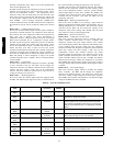
Alert Code T064 -- Circuit A Saturated Condensing
Temperature Thermistor Failure
This alert occurs when the temperature is outside the range --40_ to
240_F(--40_ to 116_C). When this occurs, the control will use
48/50PD