


8
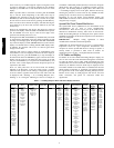
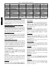
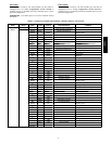
Table 3 — Application Specific Configurations
ITEM EXPANSION DEFAULT UNITS
DISPLACEMENT
VENTILATION
SINGLE ZONE
VAV
SASP Cool Supply Air Setpoint 65 dF 65 55
FS.MX Supply Fan Maximum Speed 100 % 100 100
FS.MN Supply Fan Maximum Speed 20 % 20 70
FS.VM Vent Mode Fan Speed 50 ∧F 50 50
MIN.C Min Compressor Capacity 70 % 15 70
FS.CD Fan Speed Control Demand 3 ∧F 3 3
SA.MU SASP Maximum Reset Up 10 ∧F 3 5
SA.MD SASP Maximum Reset Down --- 1 0 ∧F --- 3 --- 5
MP.MX Econ Min at Max Fanspeed 30 % 30 30
PE1.C Power Exhaust Stage 1 CFM 600 cfm 600 600
IDF.C Indoor Fan Max Speed CFM
1600 (05)
2000 (06)
cfm
1600 (05)
2000 (06)
1600 (05)
2000 (06)
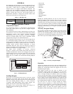
System Pilot -- Communication Space Sensor
Install the System Pilot and connect the CCN communication bus
from it to the units CCN connection on the low voltage terminal
board. Configure the unit’s CCN communication element number,
bus number, and baud rate. Refer to the System Pilot’s installation
instructions for configuring it to be used as a space temperature and
attaching it to a unit.
Gen III TEMP Monitor -- Linkage Communication
Thermostat
(33CSTMT--01)
Install the linkage thermostat. Connect the CCN communication
bus from the Stat to the CCN terminals on the field connection
terminal board located at the unit control box. Configure the unit’s
CCN communication element number, bus number, and baud rate.
Refer to the Linkage Thermostat’s installation instructions for
configuring the Stat and additional information about it.
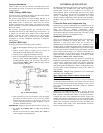
Space Humidistat Control
The humidistat input is provided on the field connection terminal
board. The Space Humidity Switch configuration,
Configuration→UNIT→RH.SW, identifies the normally open or
normally closed status of this input at LOW humidity. Humidistat
1 terminal is the 24 VAC source for dry contact and the Humidistat
2 terminal is the signal input.
Relative Humidity Sensor Control
For units with the economizer option (with the ECB --economizer
control board), the humidity sensor input is provided on the field
connection terminal board. The sensor can be used in addition to
or instead of a humidistat. The RH Sensor on OAQ Input
configuration, Configuration→UNIT→RH.S=YES, identifies that
the sensor is being used instead of an OAQ sensor. Terminal 1 is
the 24vdc loop power and Terminal 4 is the 4--20 mA signal input.
Refer to the Field Installed Accessories for more information.
CCN Communication
Configure Configuration→CCN→CCN.A to desired element
number (Default is 1). Configure Configuration→CCN→ CCN.B
to desired bus number (Default is 0). Configure
Configuration→CCN→BAUD to desired code number for baud
rate (Default is 3 = 9600 baud).
Accessories
Below are quick configuration settings for field installed
accessories. If these accessories were installed by the factory, they
will already be configured. See the Field--Installed Accessories
section, third party control, control connection tables, and CCN or
Display parameter tables for any accessories not me ntioned below
and any additional information on accessories.
Economize r
If an Economizer accessory was field installed, the unit must be
configured for it by setting Configuration→ECON→EC.EN to
YES. The default settings for the other economizer configurations
should be satisfactory. If they need to be changed, additional
information about these configuration settings can be found in the
Economizer section.
Power Exhaust
If a Power Exhaust accessory was field installed, the unit must be
configured for it by setting Configuration→ECON→PE.EN to
ENBL. The default settings for the other power exhaust
configurations should be satisfactory. If they need to be changed,
additional information about these configurations can be found in
the Power Exhaust section.
Electric Heat
If an Electric Heat accessory was field installed, the unit must be
configured for it by setting Configuration→HEAT→HT.TY to a
value of 2. The number of electric heat stages must be configured
by setting Configuration→HEAT→N.HTR per the installed
heater.
Fire Shutdown
If a Fire Shutdown or Smoke Detector accessory was field
installed, the unit must be configured for it by setting
Configuration→UNIT→FS.SW to normally open (1) or normally
closed (2) when there is not a fire alarm. Normally open (1) is the
preferred configuration.
IMPORTANT: On standard units, the fire shutdown input is the
terminals Fire Shutdown 1 and 2.
Outdoor Enthalpy
If an Outdoor Enthalpy accessory was field installed, the unit must
be configured for it by setting Configuration→ECON→EN.SW,
identifies the normally open or normally closed status of this input
when the outdoor enthalpy is low.
IAQ Switch
If an IAQ Switch accessory was field installed, the unit must be
configured for it by setting Configuration→AIR.Q→II.CF ,
identifies the normally open or normally closed status of this input
when the indoor air quality value is low (good) and also selects the
unit response to this input.
IMPORTANT: An IAQ switch cannot be used if an enthalpy
switch is already on this input.
IAQ Sensor
If an CO
2
Sensor accessory was field installed, the unit must be
configured for it by setting Configuration→AIR.Q→IA.CF
selects the unit response to this input. Default conversion to 0 to
2000 ppm.
OAQ Sensor
If an Outdoor Air Quality Sensor accessory wa s field installed, the
unit must be configured for it by setting Configuration→AIR.Q
→OA.CF selects the unit response to this input. Default
conversion to 0 to 2000 ppm.
48/50PD