


11
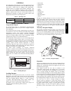
Cooling Test
The cooling (COOL) submenu is used to change output status for
testing the cooling function. The fans (FANS) and heating (HEAT)
service test outputs are reset to OFF for the cooling service test.
The digital scroll controller power test (CTLR) turns on and off the
compressor controller. The compressor capacity test (CPAC) is
used to run the compressor at a desired capacity of 15% to 100%.
If a capacity is chosen between 1 and 14, the capacity will be set to
15%. The outdoor fan will turn on to high speed when the
compressor capacity is 15% or greater. The indoor fan speed will
default to supply fan maximum speed (FS.MX) when the
compressor capacity test is first activated. The cool test fan s peed
(F.SPD) is used to change the fan speed while the compressor is
running. All normal cooling alarms and alerts are functional.
IMPORTANT: When charging the unit, both the compressor
capacity test and the cool test fan speed should be set to 100%.
Heating Test
The heating (HEAT) submenu is used to change output status for
the individual heat stages, gas or electric. The fans (FANS) and
cooling (COOL) service test outputs are reset to OFF for the
heating service test. Indoor and outdoor fans are controlled
normally to maintain proper unit operation. The indoor fan speed
will run at the configured max speed FS.MX. All normal heating
alarms and alerts are functional.
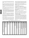
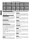
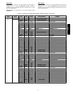
Table 5 — Service Test Modes and Submodes Directory
DISPLAY MENU/
SUB--MENU/
NAME
EXPANDED NAME VALUES
SERVICE TEST
Field Service Test Mod e On/Off
TEST
INDP Test Independent Outputs
ECON Economizer Position Test 0 to 100%
E.CAL Calibrate Economizer On/Off
PE.1 Power Exhaust 1 Test On/Of f
PE.2 Power Exhaust 2 Test On/Of f
ALRM Alarm Relay Test On/Off
CCH Crankcase Heat Test On/Off
FANS SUPPLY Test Fans
IDF VFD Power Test On/Off
F.SPD Indoor Fan Speed Test 0 to 100%
OFC.1 Outdoor Fan Relay Test On/Off
COOL Test Cooling
CTLR DigScrollCtrlPwrTest On/Off
CAPC Compressor Capacity Test 0 to 100%
F.SPD Cool Test Fan Speed 0 to 100%
HEAT Test Heating
HT.1 Heat Stage 1 Test On/Off
HT.2 Heat Stage 2 Test On/Off
THIRD PARTY CONTROL
Third party controls may interface with the unit ComfortLinkt
controls through the connections described below. See other
sections of these instructions for more information on the related
unit control and configurations.
Remote Occupancy
The remote occupancy input is provided on the field connection
terminal board (TB1). The Remote Occupancy Switch
configuration, Configuration→UNIT→RM.SW, identifies the
normally open or normally closed status of this input when
unoccupied.
S 5 = 24 VAC signal input
S 6 = 24 VAC source for dry contact
Fire Shutdown
The fire shutdown input is provided for unit shutdown in response
to a fire alarm or smoke detector. The Fire Shutdown Switch
configuration, Configuration→UNIT→FS.SW, identifies the
normally open or normally closed status of this input when there is
no fire alarm.
Input at field connection terminal board (TB1)
S Fire Shutdown 1 = 24 VAC source for dry contact
S Fire Shutdown 2 = 24 VAC signal input
Alarm Output
The alarm output is provided on the field connection terminal
board (TB1) to indicate a current alarm status. The output will be
24VAC if a current alarm exists.
S C=24VACcommon
S X = 24 VAC signal output
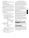
Economizer Monitoring
On field terminal board (TB1), terminals 8, 9, and 10 can be used
to monitor economizer position from a third party control system.
See economizer operation section for additional information.
In digital mode (E.CTL = 1 or 2), the economizer commanded
position can be read as a 2--10v or 4--20mA signal. TB1--8 and
TB1--9 are used as follows:
S To read a 2--10v signal, disconnect the violet wire on
TB1-- J10--8 and place volt meter device across TB1-- 8 and
TB1 --9 .
S To read a 4--20mA signal, disconnect the violet wire on
TB1-- J10--8 and the 500Ω resister at TB1--J10--6. Place amp
meter device between TB1--8 and TB1--9.
In analog mode (E.CTL = 3), the economizer position can be read
as a 2 --10v feedback signal across TB1--10 and TB1-- 9 at any time.
IMPORTANT: The violet wire and 500Ω resister must be
connected at the J10 connector as originally wired to operate the
economizer in analog mode.
Economizer Damper Contr ol
For units with the economizer option or accessory and the ECB
control board, the damper position can be directly controlled
through the IAQ sensor input provided on the field connection
terminal board. The IAQ Analog Input configuration,
Configuration→AIR.Q→IA.CF will have to set to 3 (Control
Minimum Position). When IA.CF = 3, an external 4 to 20 mA
source is used to move the damper 0% to 100% directly.
Terminal 2 = 4--20mA + signal
Terminal 3 = 4--20mA -- common
IMPORTANT: In this mode preset minimum positions
configurations are not valid. The damper position may exceed the
input position to provide economizer cooling and CO
2
sensor input
can not be used for DCV control. Refer to the Indoor Air Quality
operation section for more information.
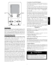
CONTROLS OPERATION
Display Configuration
The Configuration→DISP submenu is used to configure the local
display settings.
Metric Display (METR)
This variable is used to change the display from English units to
Metric units.
Language Selection (LANG)
This variable is used to change the language of the ComfortLink
display. At this time, only English is available.
48/50PD