


67
Evaporator Fan Motor Protection
Indoor-fan motors less than 5 hp are equipped with internal
overcurrent and overtemperature protection. Protection devices
reset automatically. Disconnect and lock out power when servicing
motor. Indoor-fan motors 5 hp and larger are equipped with a
manual reset, calibrated trip, magnetic circuit breaker and
overcurrent protection. Do not bypass connections or increase the
size of the breaker to correct trouble. Determine the cause and
correct it before resetting the breaker.
Condenser--Fan Motor Protection
Each condenser-fan motor is internally protected against
overtemperature.
Fuses are located in the control box and feed power to the
condenser fan motors. Always replace blown fuses with the
correct size fuse as indicated on the unit fuse label.
Saturated Suction Pressure ( SSP)
If the SSP for a particular circuit is reading below the alarm set
point for an extended period of time, that circuit will be shut down.
After 15 minutes, the alarm will automatically reset. If this alarm
occurs 3 times consecutively , the circuit will remain locked out
until an alarm reset is initiated via CCN or manually via the
Scrolling Marquee display (see Alarms and Alerts section for more
details).
Relief Devices
All units have relief devices to protect against damage from
excessive pressures (i.e., fire). These devices protect the high and
low side and are located at the suction line service port. Protect
joint during brazing operations near joint.
Compressor Sound Shield
The 48/50PD units are equipped with a compressor sound shield.
The sound shield has two parts, the compressor jacket encloses the
shell of the compressor and the base shield is installed between the
bottom of the compressor and the unit base pan. The sound shield
reduces the difference in noise levels as the compressor loads and
unloads in the frequency ranges of 200 to 2000 Hz. Since the
human speech occurs in the 200 to 2000 Hz frequency ranges the
sound shield reduces the speech annoyance caused by the loading
and unloading of the compressor.
The compressor jacket is held closed around the compressor by
Velcro tape. To r emove the compressor jacket, separate the Velcro
along the side and top of the compressor. Slide the jacket toward
the back of the compressor to remove the jacket. Make sure the
jacket is reinstalled after servicing or replacing the compressor.
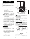
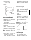
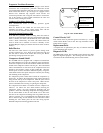
The compressor base shield is accessible when the compressor is
removed. To remove the base shield without removing the
compressor, remove one front compressor mounting bolt and
grommet. At the three remaining compressor mounting grommets,
cut the sound shield so that the base shield can be slid in the
direction of the compressor mounting bolt and grommet that was
removed. (See Fig. 39.) Cut replacement base shield a long dotted
lines as shown in Fig. 39 and reinstall in reverse direction. When
installing the base shield, place the soft side facing upward.
Reinstall compressor mounting grommet and bolt.
Remove this compressor
mounting bolt and grommet
at this location.
Slide Compressor Base Sound
Shield in this direction.
Cut Compressor Base Sound
Shield along dotted lines
COMPRESSOR BASE
SHIELD
C08664
Fig. 39 -- Base Sound Shield
Control Circuit, 24 --V
Each control circuit is protected against overcurrent by a 3.2 amp
circuit breaker . Breaker can be reset. If it trips, determine cause of
trouble before resetting.
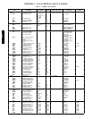
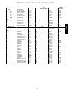
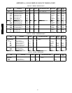
Replacement Parts
A complete list of replacement parts may be obtained from any
Carrier distributor upon request.
Diagnostic L EDs
The MBB, ECB, AUX1, IGC and DSC control boards have LED
lights for diagnostic purposes. The meanings and error codes can
be found in the the troubleshooting section of this manual.
48/50PD