


20
Quality (IAQ) section of t he Economizer Operation section above
for more details on Demand Control Ventilation (DCV).
Economizer Operation for Units Equipped with Return
Air
CO
2
Sensor Only
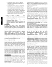
When the CO
2
sensor detects a CO
2
level or IAQ Level
(Inputs→AIR.Q→IAQ) below the AQ Differential Low
(Configuration→AIR.Q→AQD.L) value the MP.25, MP.50,
MP.75 and MP.MX points will be recalculated to new values for
MP.25, MP.50, MP.75 based on the Econ Min IAQ Position
(Configuration→AIR.Q→AQ.MN). The economizer outside air
damper will close and reduce the amount of outside air CFM to the
conditioned space based on the lower IAQ sensor readings and
indoor fan speed. The economizer outside air damper will
continue to close and reduce the amount of outside air CFM to the
conditioned space until the damper reaches user configurable Econ
Min IAQ Position (Configuration→AIR.Q→AQ.MN). This will
happen when the Commanded Fan Speed
(Outputs→FANS→F.S PD) is at the Supply Fan Maximum Speed
(Configuration→UNIT→FS.MX). When the Commanded Fan
Speed (Outputs→FANS→F.SP D) is between Supply Fan
Maximum Speed (Configuration→UNIT→FS.MX) and the
Supply Fan Minimum Speed (Configuration→UNIT→FS.MN)
the damper will operate in the shaded area of Figure 8 based on the
IAQ Level (Inputs→AIR.Q→IAQ).
Economizer Operation for Units Equipped with Return
Air
CO
2
Sensor and outside air CO
2
Sensor
The Economizer will operate similar to Economizer Operation for
Units Equipped with Return Air CO
2
Sensor Only but the IAQ
Level (Inputs→AIR.Q→IAQ) will be determined by actual
outside air CO
2
measurements instead of the 400 ppm CO
2
default
value for OAQ.
Cooling Mode Using Space Temperature Sensor T55,
T56, T58 or T59 and Humidistat (HL38MG029 or
TSTATCCPLH01--B)
Enhanced dehumidifying will be provided when a humidistat
(HL38MG029 or TSTATCCPLH01--B) is connected the PD unit
terminal strip across the R and W2 terminals (since the PD unit
does not support the use of conventional thermostat inputs the W2
terminal is reconfigured for humidity input) and Space Humidity
Switch (Configuration→UNIT→RH.SW) configuration variable
is set to 1 (Normally Open--no call to dehumidify). Relative
humidity set point is set by adjusting the dial on the HL38MG029
or TSTATCCPLH01-- B device. When the humidistat contacts
close and provide 24VAC to the W2 terminal the PD unit will reset
the Supply Air Control Point (Run Status→COOL→SA.CP) by
one degree F lower than the Supply Air Set Point
(Setpoint→SASP) or the current control point if the Supply Air
Set Point (Setpoint→SASP) has already been modified. After 5
minutes if the humidistat contacts are still closed and 24 VAC is
being supplied to the W2 terminal the PD unit will reset the Supply
Air Control Point (Run Status→COOL→SA.CP) lower by one
more degree F. This reset cycle will continue to lower the supply
air temperature every 5 minutes until the Supply Air Control Point
(Run Status→COOL→SA.CP) is equal to the Supply Air Set
Point (Setpoint→SASP) + SASP Maximum Reset Down
(Configuration→COOL→SAT→SA.MD). The unit will continue
to operate at this reduced supply air temperature control point until
the humidistat contacts open and 24VAC is no longer supplied to
the W2 terminal. When 24VAC is no longer supplied to the W2
terminal the supply air control point will be reset higher by one
degree F. After 3 minutes if the humidistat contacts are still open
and 24VAC is not being supplied to the W2 terminal PD unit will
reset the Supply Air Control Point (Run Status→COOL→SA.CP)
higher by one more degree F. This reset cycle will continue to
raise the Supply Air Control Point (Run Status→COOL→SA.CP)
every 3 minutes until the Supply Air Control Point (Run
Status→COOL→SA.CP) is equal to the Supply Air Set Point
(Setpoint→SASP) or the supply air control point if reset was being
applied due to cooling requirements that reset the Supply Air Set
Point (Setpoint→SASP). Whenever Relative Humidity Reset is
applied the space temperature is controlled by modulating the fan
speed even if the fan was locked at 100% due to (Setpoint→
SASP)
reset.
Cooling Mode Using Space Temperature Sensor T55,
T56, or T58 and Humidity Sensor (HL39ZZ007 or
33ZCSENRH--01)
Enhanced dehumidifying will be provided when a humidly sensor
(HL39ZZ007 or 33ZCSENRH--01) 4 to 20 ma control is
connected the PD unit terminal strip across the TB1--J10 pin 3 and
4, power to humidity sensor is connected to R and C, the RH
Sensor on OAQ Input (Configuration→UNIT→RH.S) is set to
YES and Space Humidity Switch
(Configuration→UNIT→RH.SW) configuration variable is set to
0. Relative humidity set point is set by changing the value of
Space RH Set point (Setpoint→RH.SP). When the relative
humidity in the space is above the Space RH Set point
(Setpoint→RH.SP) the PD unit controls will reset the supply air
temperature by one degree F lower than the Supply Air Set Point
(Setpoint→SASP) or the current control point if the Supply Air
Set Point (Setpoint→SASP) has already been modified. After 5
minutes the PD unit will reset the Supply Air Control Point (Run
Status→COOL→SA.CP) lower by one more degree F. This reset
cycle will continue to lower the Supply Air Control Point (Run
Status→COOL→SA.CP) every 5 minutes until the Supply Air
Control Point (Run Status→COOL→SA.CP) is equal to the
Supply Air Set Point (Setpoint→SASP) +SASPMaximumReset
Down (C onfiguration→COOL→ SAT→SA.MD). When the
relative humidity in the space goes below the Space RH Set Point
(Setpoint→RH.SP) -- the Space RH Deadband
(Setpoint→RH.DB) the supply air control point will be reset
higher by one degree F. After 3 minutes if the humidity sensor
reading is still below the Space RH Set Point (Setpoint→RH.SP) --
the Space RH Deadband (Setpoint→RH.DB), the PD unit will
reset the Supply Air Control Point (Run
Status→COOL
→SA.CP) higher by one more degree F. This reset
cycle will continue to raise the Supply Air Control Point (Run
Status→COOL→SA.CP) every 3 minutes until the supply air
temperature control point is equal to the Supply Air Set Point
(Setpoint→SASP) or the supply air control point if reset was being
applied due to cooling requirements that reset the Supply Air Set
Point (Setpoint→SASP).
Heating Modes
Gas Heating Mode Using Space Temperature Sensor
T55, T56, or T58 (48PD Units O nly)
For gas units, the Type of Heat Installed
(Configuration→HEAT→HT.TY) will be factory set to a value of
1.
Heat will not operate if the outdoor temperature is greater than the
value configured for the Heating Lockout Temperature
(Configuration→HEAT→HT.LO), Heat Minimum On Time
(Configuration→HEAT→MRT.H) and Heat Minimum Off Time
(Configuration→HEAT→MOT.H). Timeguards apply to both
stages of heating. Factory defaults values are 2 minute s ON and 2
minutes OFF. The Integrated Gas Controller (IGC) minimum
on--time of 1 minute will be followed even if Heat Minimum On
Time (Configuration→HEAT→MRT.H) is lower and during
Service Test.
If the indoor fan control is configured to cycle with the heating
demand by setting Fan ON When Occupied Heat Minimum On
Time (Configuration→UNIT→OC.FN) to NO, the fan will stop
after a delay configured by Fan--off Delay, Gas Heat
(Configuration→HEAT→FOD.G). The factory default for
Fan--off Delay, Gas Heat (Configuration→HEAT→FOD.G) is 45
seconds. If the IGC temperature limit switch opens within 10
minutes of the end of the gas heat cycle, the next fan off delay will
48/50PD