


5
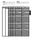
SCROLL
+
-
NAVIGATE/
EXIT
MODIFY
/
SELECT
PAGE
C06322
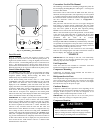
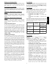
Fig. 3 -- System Pilott User Interface
Force Hierarchy
There is a hierarchy in CCN with regards to forcing a point.
Programs and devices write a force at different priority levels. A
higher level (smaller number, 1 being the highest) will override a
lower level force. The Scrolling Marquee uses a Control Force at
level 7. The Navigator writes a Service Force which is level 3.
System Pilots and Touch Pilots w rite Supervisor Forces at level 4.
Network programs can be set to write different level priority forces.
Generic Status Display Table
The GENERIC points table allows the service/installer the ability
to create a custom table in which up to 20 points from the 5 CCN
categories (Points, Config, Service--Config, Set Point, and
Maintenance) may be collected and displayed.
In the Service--Config table section, there is a tab le named
“GENERICS.” This table contains placeholders for u p to 20 CCN
point names and allows the user to decide which points are
displayed in the GENERIC points sub--table under the status
display table. Each one of these placeholders allows the input of an
8--character ASCII string. Using a CCN interface, enter the Edit
mode for the Service--Config table “GENERICS” and enter the
CCN name for each point to be displayed in the custom points
table in the order they will be displayed. When done entering point
names, download the table to the rooftop unit control.
IMPORTANT: The computer system software (ComfortVIEWt,
Service Tool, etc.) that is used to interact with CCN controls,
always saves a template of items it considers as static (e.g., lim its,
units, forcibility , 24--character text strings, and point names) after
the software uploads the tables from a control. Thereafter, the
software is only concerned with run time data like value and
hardware/force status. With this in mind, it is important that any
time a change is made to the Service--Config table “GENERICS”
(which in turn changes the points contained in the GENERIC point
table), that a complete new upload be performed. This requires that
any previous table database be completely removed first. Failure to
do this will not allow the user to display the new points that have
been created and the CCN interface will have a different table
database than the unit control.
Conventions Used in This Manual
The following conventions for discussing configuration points for
the local display (Scrolling Marquee or Navigator™ accessory) will
be used in this manual.
Point names will be written with the Mode name first, then any
submodes, then the point name, each separated by an arrow symbol
(→). Names will also be shown in bold and italics. As an example,
the Fan Status Switch which is located in the Configuration mode,
and Unit sub-mode w ould be written as Configuration→
UNIT→FN.SW.
This path name will show the user how to navigate through the
local display to reach the desired configuration. The user would
scroll through the modes and sub-modes using the up and down
keys. The arrow symbol in the path name represents pressing
ENTER to move into the next level of the menu structure.
When a value is included as part of the path name, it will be shown
at the e nd of the path name after an equals sign. If the value
represents a configuration setting, an explanation will be shown in
parenthesis after the value. As an example,
Configuration→UNIT→FN.SW = 1 (Normal Open).
Pressing the ESCAPE and ENTER keys simultaneously will scroll
an expanded text description of the point name across the display.
The expanded description is shown in the local display tables but
will not be shown with the path names in text.
The CCN point names are also referenced in the local display
tables for users configuring the unit with CCN software instead of
the local display. See Appendix A of this manual.
START-UP
IMPORTANT: Do not attempt to start unit, even momentarily,
until all items on the Start--Up Checklist (last page) and the
following steps have been completed.
Unit Preparation
Check that unit has been installed in accordance with these
installation instructions and all applicable codes.
Compressor Mounting
Compressors are internally spring mounted. Do not loosen or
remove compressor holddown bolts.
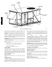
Refrigerant Service Ports
Each independent refrigerant system has a total of 3 Schrader-type
service gauge ports per circuit. One port is located on the suction
line, one on the compressor discharge line, and one on the liquid
line. Be sure that caps on the ports are tight.
Crankcase Heater(s)
Compressor crankcase heater operation varies depending on the
unit size and type. In general for all units, the crankcase heaters are
energized if there is power to the unit, the compressor is not
operating, and the ambient temperature is below 75_F.
IMPORTANT: Unit power must be on for 24 hours prior to
start--up. Otherwise, damage to compressor may result.
Compressor Rotation
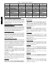
UNIT DAMAGE HAZARD
Failure to follow this caution may result in unit damage.
Improper wiring will cause compressor stoppage and alarm.
Correct wiring by switching leads as indicated below.
CAUTION
!
48/50PD