


16
a. (Configuration→ECON→UEFC = 0) -- D i s a b l e d
When UEFC = 0, unoccupied free cooling is disabled.
Cooling will only occur if the space exceeds the
unoccupied setpoints.
b. (Configuration→ECON→UEFC = 1) -- Unoccupied
When UEFC is set to 1, unoccupied free cooling can
occur throughout the entire unoccupied period. The
space temperature must be higher then the mid--point
between the occupied cooling and heating set points.
c. (Configuration→ECON→UEFC = 2) -- Preoccupancy
When UEFC is set to 2, unoccupied free cooling can
only occur when the time until the next occupied period
is less than the Free Cool PreOcc Time (FC.TM) in
minutes.
2. Free Cool PreOcc Time
(Configuration→ECON→FC.TM)
FC.TM is the configuration that determines how many
minutes before occupancy that free cooling can occur when
set for Preoccupancy (UEFC = 2).
3. 1.Free Cool Low Temp Limit
(Configuration→ECON→FC.LO)
Unoccupied free cooling cannot occur if the Outdoor Air
Temperature (Temperature→ AIR.T→ OAT) is less than
FC.LO.
Power
Exhaust
To enable power exhaust set Power Exhaust Installed
(Configuration→ECON→PE.EN) to YES. On the 48/50PD--05
and 06 size units both power exhaust fans are wired together and
are controlled by the configuration Power Exhaust Stage1 CFM
(Configuration→ECON→PE1.C). When the Indoor Fan Max
Speed CFM (Configuration→ECON→IDF.C) is set to the correct
supply duct CFM (either by fan tables or air balance report) the
control will calculate the outside air CFM based on outside air
damper position a nd Commanded Fan Speed
(Outputs→FANS→F.S PD) to turn on the power exhaust when the
calculated outside air CFM reaches Power Exhaust Stage1 CFM
(Configuration→ECON→PE1.C). The power exhaust will turn
off when the calculated outside air CFM falls below Power
Exhaust Stage1 CFM (Configuration→ECON→PE1.C).The
Power Exhaust Stage2 CFM (Configuration→ECON→PE2.C) is
not currently used on the 48/50PD--05 and 06 units.
Indoor Air Quality (IAQ)
The ComfortLink TM control has the capability for several
methods of demand ventilation control. Indoor air quality is
typically measured using a CO2 sensor whose measurements are
displayed i n parts per million (ppm). O utdoor air quality may be
measured with a CO2 sensor for indoor--outdoor differential
demand ventilation control, or with other sensor types for the
outdoor air lockout function. The factory--installed indoor air
quality CO2 sensor is mounted in the return section. A
field--installed indoor air quality CO2 sensor may be mounted in
the return or directly in the occupied space, per job requirements.
The indoor air quality modes of operation can be affected by the
IAQ Analog Input Config (Configuration→ AIR.Q→ IA.CF),
IAQ Switch Input Config (Configuration→ AIR.Q→ IA.CF),
OAQ Analog Input Config (Configuration→ AIR.Q→ OA.CF)
and other related fan and limit configurations as described below.
IAQ (Analog
Input)
The ComfortLink TM control is configured for indoor air quality
sensors which provide 4 to 20 mA signal for 0 to 2000 ppm CO2.
If the sensor being used has a different range, the ppm display
range must be reconfigured by entering new values for the IAQ
Sensor Value at 4mA (Configuration→AIR.Q→I.4M) and IAQ
Sensor Value at 20mA (Configuration→AIR.Q→I.20M).
IA.CF = 0 (No IAQ)
IA.CF = 0 signifies that there is no IAQ sensor installed. The
damper will operate at the Econ Min at Max Fan Speed
(Configuration→ECON→MP.MX) when the fan is at Supply Fan
Maximum Speed (Configuration→UNIT→FS.MX) and the
damper position will vary at other fan speeds as described in the
Cooling Mode with Economizer section below when the space is
occupied and the indoor fan is on.
IA.CF = 1 (DCV)
When IA.CF = 1 the IAQ algorithm is set for Demand Control
Ventilation (DCV). During DCV, the damper modulates between
two user configurations depending upon the relationship between
the Indoor Air Quality (IAQ) and the Outdoor Air Quality (OAQ).
The lower of these two positions is referred to as the Econo Min
IAQ Position (Configuration→AIR.Q→AQ.MN) while the higher
is referred to as the Econ Min at Max Fan Speed
(Configuration→ECON→MP.MX). The Econo Min IAQ
Position (Configuration→AIR.Q→AQ.MN) should be set to an
economizer position that brings in enough fresh air to remove
contaminates and CO2 generated by sources other than people.
The Econ Min at Ma x Fan Speed
(Configuration→ECON→MP.MX) should be set to an
economizer position that brings in fresh air to remove contaminates
and CO2 generated by all sources including people when the
indoor fan is operating at the Supply Fan Maximum Speed
(Configuration→UNIT→FS.MX). The Econ Min at Max Fan
Speed (C onfiguration→ECON→MP.MX) value is the design
value for maximum occupancy.
The ComfortLink TM control will begin to open the damper from
the Econo Min IAQ Position (Configuration→AIR.Q→AQ.MN)
position when the IAQ level begins to exceed the Outdoor Air
Quality (OAQ) level by a configurab le amount. This amount is
referred to as AQ Differential Low
(Configuration→AIR.Q→AQD.L). When the differential
between IAQ and OAQ reaches AQ Differential High
(Configuration→AIR.Q→AQD.H), the economizer position will
be at the Econ Min at Max Fan Speed
(Configuration→ECON→MP.MX) when the indoor fan speed is
at Supply Fan Maximum Speed
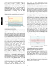
(Configuration→UNIT→FS.MX). When the IAQ/OAQ
differential is between AQ Differential Low
(Configuration→AIR.Q→AQD.L) and AQ Dif ferential High
(Configuration→AIR.Q→AQD.H), the control will modulate the
damper between Econ Min at Max Fan Speed
(Configuration→ECON→MP.MX) and Econo Min I AQ Position
(Configuration→AIR.Q→AQ.MN) in a linear manner as shown
in Figure 3. At other fan speeds the economizer damper will
operate in the shaded area between the two economizer position
curves but at the actual fan speed as indicated by Commanded Fan
Speed (Outputs→FANS→F.SPD ).
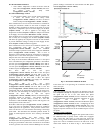
IA.CF = 2 (Override IAQ)
When IA.CF = 2, the IAQ algorithm maintains the damper at Econ
Min at Max Fan Speed (Configuration→ECON→MP.MX) when
the indoor fan speed is at Supply Fan Maximum Speed
(Configuration→UNIT→FS.MX) or in the shaded area of Figure
3 when the indoor fan speed is at the Commanded Fan Speed
(Outputs→FANS→F.S PD) until the override condition triggers.
The override triggers when the IAQ/OAQ differential is greater
than AQ Differential High
(Configuration→AIR.Q→AQD.H).
The IAQ Override Position (Configuration→AIR.Q→OVR.P).
The economizer damper will return to the Econ Min at Max Fan
Speed (Configuration→ECON→MP.MX) or MP.MX curve at
other fan speeds when the IAQ/OAQ differential is less than the
AQ Differential Low (Configuration→AIR.Q→AQD.L).
The override algorithm will operate whenever the building is
occupied and the indoor fan is operating or whenever the IAQ
algorithm has caused the indoor fan to operate. The IAQ Analog
Fan Config (Configuration→AIR.Q→IA.FN) determines whether
or not the IAQ algorithm can turn on the indoor fan.
If the indoor fan is not operating, the economizer position will be
zero. If the override is not active and the building is unoccupied,
the economizer position will be zero. The damper position may
48/50PD