


22
will not be interrupted to the burners and heating will continue.
Once modified, the fan on delay will not change back to 45
seconds unless power is reset to the control. When the indoor fan
turns on after the 40 or 45 second delay the indoor fan will run at
100% fan speed.
Gas Heat
Staging
When additional heat is required, power is supplied to the second
stage of the main gas valve. When the space temperature is 0.5F
above the Occupied Heat Set Point (Setpoint→OHSP) or
Unoccupied Heat Set Point (Setpoint→UHSP) power is removed
from the second stage of the main gas valve and to the IGC W1
terminal. Both stage 1 and stage 2 of the gas valve closes,
interrupting the flow of gas to the main burners.
Gas Heat Shut
Down
If power to the IGC W1 terminal lasted less than 1 minute, the
heating cycle will not terminate until 1 minute after power is
applied to the W1 terminal of the IGC board. If the over
temperature limit opens after the indoor motor is stopped within 10
minutes of W 1 becoming inactive, on the next cycle the time w ill
be extended by 15 seconds. The maximum delay is 3 minutes.
Once modified, the fan off delay will not change back to 45
seconds unless power is reset to the control. A LED indicator is
provided on the IGC to monitor operation. The IGC is located in
the gas burner section and can be accessed by opening the gas
access door. During normal operation, the LED is continuously
on.
Gas Heat with
Economizer
When there is a call for heat as described above the indoor fan will
operate at the Supply Fan Maximum Speed
(Configuration→UNIT→FS.MX) configuration setting and the
economizer outdoor air damper will move to the Econ Min at Max
Fan Speed (Configuration→ECON→MP.MX) position. The
economizer outdoor air damper is closed when the indoor fan is
not operating.
Electric Heating Mode Using Space Temperature
Sensor T55, T56, or T58 (50PD Units Only)
For electric heat units with factory i nstalled e lectric heat, the T ype
of Heat Installed (Configuration→HEAT→HT.TY) will be
factory set to a value of 2 and the Number of Heat Stages
(Configuration→HEAT→N.HTR) will be factory set to match the
installed heater. If electric heat is installed in the field the value for
Number of Heat Stages (Configuration→HEAT→N.HTR) must
be changed to match the number of heat stages installed.
Heat will not operate if the outdoor temperature is greater that the
value configured for the Heating Lockout Temperature
(Configuration→HEAT→HT.LO), Heat Minimum On Time
(Configuration→HEAT→MRT.H) and Heat Minimum Off Time
(Configuration→HEAT→MOT.H). Timeguards apply to both
stages of heating. Factory defaults values are 2 minute s ON and 2
minutes OFF.
If the indoor fan control is configured to cycle with the heating
demand by setting Fan ON When Occupied Heat Minimum On
Time (Configuration→UNIT→OC.FN) to NO, the fan will stop
after a delay configured by Fan-- off Delay, Elect Heat
(Configuration→HEAT→FOD.E). The factory default for
Fan--off Delay, Elect Heat (Configuration→HEAT→FOD.E) is
30 seconds.
The electronic control uses information from the space sensor to
determine the number of heat stages required. Once the number of
stages needed for heating is determined, either Heat Stage 1 Relay
(Outputs→HEAT→HT.1), or Heat Stage 1 Relay
(Outputs→HEAT→HT.1) and Heat Stage 2 Relay
(Outputs→HEAT→HT.2) outputs will be turned on. See Gas
Heating Mode Using Space Temperature Sensor for more
information.
Supply--Air Temperature Sensor (SA
T)
The SAT Heat Mode Sensing
(Configuration→HEAT→SAT→SAT.H) affects the Supply Air
Temperature (Temperatures→AIR.T→SAT) value displayed. This
configuration is accessible via the Scrolling Marquee on the SAT
Heat Mode Sensing (Configuration→HEAT→SAT→SAT.H).
When the SAT Heat Mode Sensing
(Configuration→HEAT→SAT→SAT.H) =DSBL, the Supply Air
Temperature (Temperatures→AIR.T→SAT) value on the
Scrolling Marquee and the CCN tables will be forced to zero when
heat outputs come ON and for 5 minutes after. The default Supply
Air Temperature (Temperatures→AIR.T→SAT) location is at the
fan inlet, upstream of the heat section.
When the SAT Heat Mode Sensing
(Configuration→HEAT→SAT→SAT.H) = ENBL, the Supply
Air Temperature (Temperatures→AIR.T→SAT) sensor reading is
displayed at the Scrolling Marquee and the CCN tables during
heating mode. This setting should only be used if the original SAT
sensor wires are rem oved from the Main Base Board (MBB) and
replaced by an accessory SAT sensor located in the supply duct
downstream of the heat section. There are then two supply air
temperature limits that become active, the Maximum SAT Lower
Level (Configuration→HEAT→SAT→SAM.L) the Maximum
SAT Upper Level (Configuration→HEAT→SAT→SAM.U).
Any time the supply air temperature rises above the Maximum
SAT Lower Level (Configuration→HEAT→SAT
→SAM.L) the
heat staging will be limited to what is currently on and no
additional stages can be added until the supply air temperature falls
below the Maximum SAT Lower Level
(Configuration→HEAT→SAT→SAM.L). If the supply air
temperature rises above the Maximum SAT Upper Level
(Configuration→HEAT→SAT→SAM.U), then heating will be
reduced by removing a heat stage. That stage can not be added
again until the Supply Air Temperature
(Temperatures→AIR.T→SAT) falls below the Maximum SAT
Lower Level (Configuration→HEAT →SAT→SAM.L).Ifthe
supply air temperature stays above the Maximum SAT Upper
Level (Configuration→HEAT→SAT→SAM.U), then another
stage will be rem oved after the Heat Stage Decrease Time
(Configuration→HEAT→H.DEC).
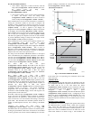
Temperature Compensated Start
This logic is used when the unit is in the unoccupied state. The
control will calculate early S tart Bias time based on Space
Temperature deviation from the occupied cooling and heating set
points. This will allow the control to start the unit so that the space
is at conditioned levels when the occupied period starts. This is
required for ASHRAE 90.1 compliance.
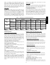
Setting Up the System
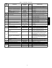
The settings for temperature compensated start can be found in the
local display under Configuration→UNIT.
ITEM EXPANSION RANGE UNITS CCN POINT
TCS.C
Temp.Cmp.Strt.Cool Factr 0 --- 60 min TCSTCOOL
TCS.H
Temp.Cmp.Strt.Heat Factr 0 --- 60 min TCSTHEAT
Temp Comp Strt Co ol Factr (TCS.C)
This is the factor for the start time bias equation for cooling.
Temp Comp Strt Heat Factr (TCS.H)
This is the factor for the start time bias equation for heating.
IMPORTANT: Temperature compensated start is disabled when
these factors are set to 0.
48/50PD