


34
Heating Troubleshooting
Use the unit Scrolling Marquee display or a CCN device to view
the heating status display and the heating diagnostic display (see
Appendix A) for information on the heating operation. Check the
current alarms and alarm history for any heating alarm codes and
correct any causes. (See Table 12.) Verify any unique control
configurations per installed site requirements or accessories. If
alarms conditions are corrected and cleared, operation of the heat
stages and indoor fan may be verified by using the Service Test
mode. (See Table 5.)
Gas Heat (48PD Units Only)
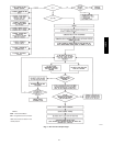
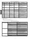
See Table 12 for general gas heating service analysis. See Fig. 9 for
service analysis of the IGC board logic. Check the status LED on
the IGC board for any flashing alarm codes and correct any causes.
(See Table 13.)
Electric Heat (50PD Units Only)
See Table 14 for electric heating service analysis.
Variable Frequency Drive (VFD) Troubleshooting
The VFD must be in “Auto” mode and when commanding it to
100% the voltage signal should be 10vdc across AI1 and AIGND.
Verify all parameters are correct to factory defaults. See Appendix
B for parameters and additional troubleshooting.
Phase Loss Protection
The phase loss protection option will monitor the three-phase
electrical system to provide phase reversal and phase loss
protection.
Phase Reversal Protection
If the control senses an incorrect phase relationship, the relay (K1)
will be de-energized (opening its contact). If the phase relationship
is correct, the relay will be energized. The control has a self-bypass
function after a pre-set time. If the control determines that the three
phases stay in a correct relationship for 10 consecutive minutes, the
relay will stay energized regardless of the phase sequence of three
inputs as long as 24-vac control voltage is applied. This self-bypass
function will be reset if all three phases are restored in a phase loss
event.
Phase Loss Protection
If the reverse rotation board senses any one of the three phase
inputs has no AC voltage, the relay will be de--energized (opening
its contact). This protection is always active as long as 24-vac
control voltage is applied, and is not affected by the self by-pass
function of the phase sequence monitoring function. However, in
the event of phase loss, the relay will be re-energized only if all
three phases are restored and the three phases are in the correct
sequence.
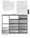
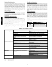
A red LED is provided to indicate the function of the board. See
the table below.
LED STATUS FUNCTION
On Continuously Relay contact closed (normal operation).
Blinking
Relay contact open (phase loss or phase
reversal has occurred) --- No power will be
supplied to the control system.
Off 24 vac control power not present (off).
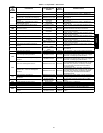
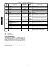
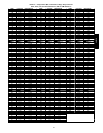
Table 12 — Ga s Heating Service Analysis
PROBLEM CAUSE REMEDY
Burners Will Not Ignite. Unit is not configured for heat. Check heating configurations using ComfortLinkt Scrolling
Marquee.
Active alarm. Check active alarms using ComfortLinkt Scrolling Marquee and
the IGC alert flash codes.
No power to unit. Check power supply, fuses, wiring, and circuit breakers.
No power to IGC. Check fuses and plugs.
Heaters off due to time guard to prevent short
cycling.
Check active alarms using ComfortLinkt Scrolling Marquee and
the IGC alert flash codes.
Occupancy schedule set point not calling for
Heating.
Check using ComfortLinkt Scrolling Marquee.
No gas at main burners. Check gas line for air and purge as necessary. After purging gas
line of air, allow gas to dissipate for at least 5 minutes before
attempting to re---light unit.
Water in gas line. Drain water and install drip.
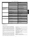
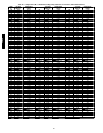
Inadequate Heating. Dirty air filters. Replace air filters.
Gas input too low. Check gas pressure at manifold. Refer to gas valve adjustment in
the Service section.
Occupancy schedule set point set too low. Check setpoints and adjust if necessary.
Unit undersized for load. Decrease load or increase of size of unit.
Restricted or low airflow. Remove restriction, verify proper fan speed operation, and check
SAT compared to the SAT heating limits.
Too much outdoor air. Check economizer position and configuration. Adjust minimum
position if needed using ComfortLink Scrolling Marquee. Verify
proper fan speed operation.
Limitswitchcyclesmainburners. Check rotation of blower and temperature rise of unit. Adjust as
needed.
Poor Flame
Characteristics.
Incomplete combustion (lack of combustion air)
results in: Aldehyde odors, CO, sooting flame, or
floating flame.
Check all screws around flue outlets and burner compartment.
Tighten as necessary.
Cracked heat exchanger, replace.
Unit is over---fired, reduce input. Adjust gas line or manifold
pressure.
Check vent for restriction. Clean as necessary.
Check orifice to burner alignment.
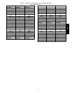
Burners Will Not Turn Off. Unit is in Minimum on---time. Check using ComfortLinkt Scrolling Marquee and the IGC alert
flash codes.
Unit running in Service Test mode. Check using Com fortLinkt Scrolling Marquee.
Main gas valve stuck. Turn off gas supply and unit power. Replace gas valve.
LEGEND
IGC -- Integrated Gas Controller
SAT -- Supply Air Temperature
48/50PD