


6
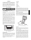
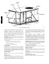
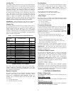
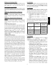
BASEPAN CONNECTIONS
ACCESS PANEL
FILTER ACCESS DOOR
GAS SECTION
ACCESS
CONDENSER COIL
ACCESS PANEL
INDOOR MOTOR
ACCESS DOOR
CONTROL BOX
AND
COMPRESSOR
ELECTRICAL
OPTIONS PANEL
OUTDOOR AIR
SCREEN
(HIDDEN)
C07002
Fig. 4 -- Panel and Filter Locations
On 3-phase units, it is important to be certain the compressors are
rotating in the proper direction. To determine whether or not
compressors are rotating in the proper direction, use a
phase-rotation meter on the unit input power to check for
L1-L2-L3 or clockwise rotation or use the Service Test mode to
energize a compressor. If the compressor is rotating in the wrong
direction, the controls will stop the compressor and display alarm
for “Circuit A Failure to Pressurize.”
IMPORTANT: Indoor or outdoor fan rotation direction may not
indicate proper input power phase sequence, as some 3-phase units
use single-phase fan motors.
To correct the wrong compressor rotation direction, perform the
following procedure:
1. Turn off power to the unit and lock out the power.
2. Switch any two of the incoming unit power leads.
3. Turn on power to the unit.
4. Verify corrected compressor rotation.
Power Supply
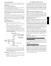
All 208/230-v units are factory wired for 230-v power supply. If
the 208/230-v unit is to be connected to a 208-v power supply, the
transformers (TRAN1 and TRAN2) must be rewired by moving
the wire from the 230-volt connection and moving to the 200-volt
terminal on the primary side of the transformer. Refer to unit label
diagram for additional information.
Internal Wiring
Check all electrical connections in unit control boxes; tighten as
required.
Evaporator Fan
Fan belt and variable pulleys are factory--installed, but may need to
be adjusted for specific applications. Be sure that the fans rotate in
the proper direction. See Appendix C for unit specific fan
performance data. See Appendix D for unit specific air quality
limits, evaporator fan motor specifications, FIOP static pressures,
and fan RPM for various motor pulley settings. Appendix C and D
are based on 100% fan speed (VFD at 60Hz). To alter fan
performance, see Evaporator Fan Performance Adjustment in the
Service section.
The Supply Fan Minimum Speed
(Configuration→UNIT→FS.MN) and the Supply Fan Maximum
Speed ( Configuration→UNIT→FS.MX) can also be used to alter
fan performance. The fan should run at the maximum fan speed
when setting up the application design point. The unit is equipped
with a Variable Frequency Drive (VFD). The VFD’s settings
should not be used for adjusting fan performance. Specific VFD
information can be found in Appendix B.
IMPORTANT: When setting up and starting the unit, the heating
minimum CFM requirements must be upheld when changing belts,
pulleys, and configurations. During heating mode, the fan speed is
always set to Supply Fan Maximum Speed (FS.MX).
Condenser Fans and Motors
Condenser fans and motors are factory set. Refer to Condenser-Fan
Adjustment section as required.
Return--Air Filters
Check that correct filters are installed i n filter tracks (see Physical
Data table in Installation Instructions). Do not operate unit without
return-air filters.
IMPORTANT: For units with 4-in. filter option, units are shipped
with standard 2-in. filters. To install 4-in. filters, the filter spacers
must be removed.
Outdoor--Air Inlet Screens
Outdoor-air inlet screens must be in place before operating unit.
48/50PD