


59
Carrier Accessory Kits
There are specific accessory kits sold for various field installed
accessories. These kits vary based on model, size, voltage,
manufacture date, and duct orientation. Some of these kits include
Economizer, Power Exhaust, and Electric Heat. Refer to the
Controls Quick Set--Up section for configuration and more
information on these accessories.
Two--Position Damper
The two-position outdoor air damper accessory usage depends on
model size and return duct orientation. This accessory wires
directly into the low voltage circuit for the indoor fan control. No
other control configuration is needed.
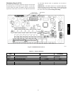
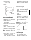
Indoor Air Quality
The indoor air quality (IAQ) sensor (part no. 33ZCSENCO2) is a
field-installed accessory which measures CO
2
levels in the air.
When installing this sensor, an ECB board must be installed and
the unit must be configured for IAQ use by setting
Configuration→AIR.Q→IA.CF to a value of 1, 2, or 3. See the
Indoor Air Quality section for more information.
TB1 --2 4--20 mA Input.......
TB1 --3 Sensor Common.......
TB1-- R 24 VAC Output......
TB1 -- C Common (GND)......
Outdoor Air Quality
The outdoor air quality (OAQ) sensor is a field-installed accessory
that measures CO
2
levels in the air. When installing this sensor, an
ECB board must be installed and the unit must b e configured for
OAQ use by setting Configuration→AIR.Q→OA.CF to a value
of 1 or 2. See the Indoor Air Quality section for more information.
TB1 --4 4--20 mA Input.......
TB1 --3 Sensor Common.......
TB1-- R 24 VAC Output......
TB1 -- C Common (GND)......
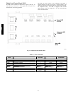
Smoke Detectors
The smoke detectors are field-installed accessories. These detectors
can detect smoke in either the return air (part no.
CRSMKDET003A00) or supply and return air (part no.
CRSMKSUP002A00). When installing either detector, the unit
must be configured for fire shutdown by setting
Configuration→UNIT→FS.SW to normally open (1) or normally
closed (2).
TB1-- Fire Shutdown-- 1 Dry Contact Source....
TB1-- Fire Shutdown--2 Discrete Input to Board....
TB1-- R 24 VAC Output................
TB1 -- C Co mmon (GND)................
Filter Status
The filter status accessory (part no. CRSTATUS002B00) is a
field-installed accessory . This accessory detects plugged filters.
When installing this accessory, the unit must be configured for
filter status by setting Configuration→UNIT→FL.SW to
normally open (1) or normally closed (2). Normally open (1) is the
preferred configuration. Filter status wires are pre-run in the unit
harness and located near the switch installation location. Refer to
the Filter Accessory Installation Instructions for more information.
Fan Status
The fan status accesso ry (part no. CRST ATUS003B00) is a
field-installed accessory. This accessory detects when the indoor
fan is blowing air. When installing this accessory, the unit must be
configured for fan status by setting
Configuration→UNIT→FN.SW to normally open (1) or
normally closed (2). Normally open (1) is the preferred
configuration. Fan status wires are pre-run in the unit harness and
located near the switch installation location. Refer to the Fan
Accessory Installation Instructions for more information.
IMPORTANT: The Fan Status terminals on TB1 are NOT to be
used.
Enthalpy Sensors
The enthalpy accessories (part no. CRENTSNG002A00 and
CRENTDIF002A00) are field-installed accessories. The first
accessory (outdoor air only) determines when the enthalpy is low
relative to a fixed reference. Adding the second accessory (return
air) compares the enthalpy between the outdoor and return
airstreams. In each case, the enthalpy 4 to 20 mA signals are
converted to a switch output which is read by the ECB. When
installing this accessory, the unit must be configured for
enthalpy-based control by setting
Configuration→ECON→EN.SW to normally open (1). Normal
status is an active switch which tells the control that enthalpy is
LOW. The actual switch terminal LOW is normally closed. Refer
to the Enthalpy Kit Installation Instructions for more information
on its installation.
Return/Supply Air Temperature Sensor
The temperature sensor (part no. 33ZCSENSAT) is a field-installed
accessory which may be installed on the common return air duct
and/or the common supply air duct near the unit. The duct supply
air temperature (SAT) may be used to replace the SAT sensor that
is internal to the unit. A supply duct SAT measurement is valid for
heating mode display while the factory-standard internal SAT is
not valid for heating due to its location upstream of the heating
section. When installing the supply duct SAT, the unit must be
configured by setting Configuration→UNIT→SAT.H to ENBL.
A SAT sensor in the supply duct is the preferred configuration for
systems with Carrier variable volume and temperature (VVT®)
accessory controls.
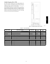
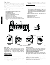
Space Humidistat
The Space Humidistat (part no. ----HL ----38MG-- 029) is a wall
mounted device with an adjustable setpoint to control humidity
levels. The humidistat input is provided on the field connection
terminal board. The Space Humidity Switch configuration,
Configuration
→
UNIT
→
RH.SW, identifies the normally open or
normally closed status of this input at LOW humidity.
TB1 --R 24 VAC Dry Contact Source......
TB1 --W2 Discrete Input to Board.....
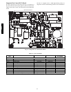
Space Humidity Sensor
The space relative humidity sensor (part no. 33ZCSENDRH--01
duct mount or 33ZCSENSRH--01 wall mount) is a field --installed
accessory. The space relative humidity (RHS) may be selected for
use if the outdoor air quality sensor (OAQ) is n ot used an d an
economizer board is installed. When installing the relative
humidity sensor, the unit must be configured by setting
Configuration
→
UNIT
→
RH.S to YES.
TB1 --1 24 VDC Loop Power.......
TB1-- 4 4--20 mA Input Signal.......
SERVICE
ELECTRICAL SHOCK HAZARD
Failure to follow this warning could cause personal
injury or death.
Before performing service or maintenance operations
on unit, turn off main power switch to unit and install
lockout tag. Ensure electrical service to rooftop unit
agrees with voltage and amperage listed on the unit
rating plate.
!
WARNING
48/50PD