


66
High Altitude
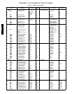
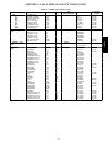
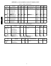
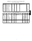
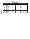
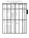
For high altitude applications greater than 2,000 ft the heat input
rate should be reduced. The higher the altitude is above sea level,
the less oxygen is in the air. See Table 8 for orifice sizing. A high
altitude kit is available to convert unit for altitudes up to 7,000 ft.
Main Burners
For all applications, main burners are factory set and should require
no adjustment.
Main Burner Removal
1. Shut off (field-supplied) manual main gas valve.
2. Shut off power to unit.
3. Open gas section access door.
4. Disconnect gas piping from gas valve inlet.
5. Remove wires from gas valve.
6. Remove wires from rollout switch.
7. Remove sensor wire and ignitor cable from IGC board.
8. Remove 2 screws that hold the burner assembly to vestibule
plate.
9. Rotate the burner/manifold assembly to the right, away
from the flue extension and lift burner/manifold assembly
out of unit.
Cleaning and Adjustment
1. Remove burner rack from unit as described in Main Burner
Removal section above.
2. Inspect burners, and if dirty, remove burners from rack. The
two outer burners have the flame crossover closed off in
order to prevent gas flow from exiting the sides of the
burner assembly. To prevent ignition problems, make sure
the outer burners are returned to their original position when
done servicing.
3. Using a soft brush, clean burners and crossover port as
required.
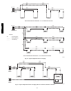
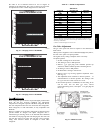
4. Adjust spark gap. (See Fig. 38.)
5. Reinstall burners on rack.
6. Reinstall burner rack as described above.
E
E
AA
B
B
25.4
MAX. TYP.
SPARK GAP
0.120 TO 0.140”
[3.05 TO 3.56]
D
D
E-E
SECTION
SCALE 2:1
D-D
SECTION
B-B
SECTION
SCALE 1:1
A-A
SECTION
SCALE 1:1
C-C
SECTION
C
C
SPARK GAP
0.181”
[4.6]
C06269
Fig. 38 -- Spark Gap Adjustment
Filter Drier
Replace filter drier whenever refrigerant system is exposed to
atmosphere. Only use factory specified liquid-line filter driers with
working pressures no less than 650 psig. Do not install a
suction-line filter drier in liquid line. A liquid-line filter drier
designed for use with Puron® refrigerant is required on every unit.
Protective Devices
Compressor Rotation
Overcurrent
Each compressor has internal line break motor protection.
Overtemperature
Each compressor has an internal protector to protect it against
excessively high discharge gas temperatures.
High--Pressur e Switch
If the high-pressure switch trips, the compressor will shut down
and the current sensor (3-phase units only) will not detect current.
See the Current Sensor section below for more information.
Current Sensor (CS) (3--Phase Units Only)
The purpose of the CS is to detect losses in compressor power.
After detecting a loss in compressor power, unit control locks out
the compressor for 15 minutes. After 15 minutes, the alarm will
automatically reset. If this alarm occurs 3 times consecutively, the
compressor will remain locked out until an alarm reset is initiated
via CCN or manually via the Scrolling Marquee display (see
Alarms and Alerts section for more details).
IMPORTANT: The current sensor is not currently used in the
48/50PD, but reserved for future implementation.
48/50PD