


21
be extended by 15 seconds. The maximum delay is 3 minutes.
Once modified by the IGC, the fan off delay will not change back
to the configured Fan--off Delay , Gas Heat
(Configuration→HEAT→FOD.G) unless power is reset to the
control.
A light emitting diode (LED) is provided on the IGC to indicate
status. During normal operation the LED is continuously on. See
the Troubleshooting section if the LED is off or flashing. The IGC
is located behind the gas section access panel door. See Figure 8 or
9 for location.
The 48/50PD unit control will switch automatically between
cooling and heating to maintain space temperature. To minimize
unnecessary changes there is a 10 minute Mode Select Timeguard
(Operating Modes→HEAT→MS.TG) after the last stage of
cooling turns off and before the heating is allowed.
The unit tries to maintain the space temperature at the Occupied
Heat Setpoint (Setpoint→OHSP) or the Unoccupied Heat Setpoint
(Setpoint→UHSP). See the Occupancy Determination section for
factors that affect the Currently Occupied (R un
Status→VIEW→OCC) parameter. Heating Demand (Operating
Modes→HEAT→SPT→DMD.H) is equal to the occupied or
unoccupied set point minus the Space Temperature (Operating
Modes→HEAT→SPT→SPT) [DMD.H = Setpoint -- SPT].
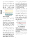
Two methods are used to add and remove stages of heating for
48PD units. The first method causes the unit to operate around its
steady state number of stages. For example, if the correct number
of stages is between 0 and 1, this method will cause the f irst stage
to cycle. If the correct number of stages is between 1 and 2, this
method will cause the second stage to cycle. The second method
causes the unit to find the steady --state number of stages. Details of
these methods are provided below.
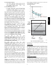
The control uses two methods to add a stage of heating. The first
method will add a stage of heating when the Heating Demand
(Operating Modes→HEAT→SPT→DMD.H) plus the change in
Spacetemp Trend (Operating Modes→HEAT→SPT→TRND)
times the Heat Thermal Lag Factor (Operating
Modes→HEAT→
SPT→H.LAG) is greater than the SPT Heat
Demand (+) Level (Operating Modes→HEAT →SPT→HT.PD)
[DMD.H + change TRND * H.LAG > HT.PD].
The second method will add a stage of heating when Heat Demand
(Operating Modes→HEAT→SPT→DMD.H) is greater that the
SPT Heat Demand (+) Level (Operating
Modes→HEAT→SPT→HT.PD) plus 0.5 degrees F [DMD.H >
HT.PD + 0.5] and the heat demand is changing at a rate greater
than 0.3 degrees F per minute.
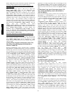
The control uses two methods to remove a stage of heating. The
first method will remove a stage of heating when the Heating
Demand (Operating Modes→HEAT→SPT→DMD.H) plus the
change in Spacetemp Trend (Operating
Modes→HEAT→SPT→TRND) times th e Heat Thermal Lag
Factor (Operating Modes→HEAT →SPT→H.LAG)islessthan
the SPT Heat Demand (--) Level (Operating
Modes→HEAT→SPT→HT.ND) [DMD.H + change TRND *
H.LAG < HT.ND].
The second method will remove a stage of heating when Heat
Demand (Operating Modes→HEAT→
SPT→DMD.H) is less that
the SPT Heat Demand (--) Level (Operating
Modes→HEAT→SPT→HT.ND) minus 0.5 degrees F [DMD.H <
HT.PD -- 0.5] and the heat demand is changing at a rate greater
than 0.3 degrees F per minute.
Configurable delays also apply when adding stages per Heat Stage
Increase Time (C onfiguration→HEAT →H.INC) or removing
stages per Heat Stage Decrease Time
(Configuration→HEAT→H.DEC). Heat Minimum On Time
(Configuration→HEAT→MRT.H) and Heat Minimum Off Time
(Configuration→HEAT→MOT.H) also apply.
Supply--Air Temperature Sensor (SA
T)
The SAT Heat Mode Sensing
(Configuration→HEAT→SAT→SAT.H) affects the Supply Air
Temperature (Temperatures→AIR.T→SAT) value displayed. This
configuration is accessible via the Scrolling Marquee on the SAT
Heat Mode Sensing (Configuration→HEAT→SAT→SAT.H).
When the SAT Heat Mode Sensing
(Configuration→HEAT→SAT→SAT.H) =DSBL, the Supply Air
Temperature (Temperatures→AIR.T→SAT) value on the
Scrolling Marquee and the CCN tables will be forced to zero when
heat outputs come ON and for 5 minutes after. The default Supply
Air Temperature (Temperatures→AIR.T→SAT) location is at the
fan inlet, upstream of the heat section.
When the SAT Heat Mode Sensing
(Configuration→HEAT→SAT→SAT.H) =ENBL, the Supply Air
Temperature (Temperatures→AIR.T→SAT) sensor reading is
displayed at the Scrolling Marquee and the CCN tables during
heating mode. This setting should only be used if the original SAT
sensor wires are rem oved from the Main Base Board (MBB) and
replaced by an accessory SAT sensor located in the supply duct
downstream of the heat section. There are then two supply air
temperature limits that become active, the Maximum SAT Lower
Level (Configuration→HEAT→SAT→SAM.L) the Maximum
SAT Upper Level (Configuration→HEAT→SAT→SAM.U).
Any time the supply air temperature rises above the Maximum
SAT Lower Level (Configuration→HEAT→SAT
→SAM.L) the
heat staging will be limited to what is currently on and no
additional stages can be added until the supply air temperature falls
below the Maximum SAT Lower Level
(Configuration→HEAT→SAT→SAM.L). If the supply air
temperature rises above the Maximum SAT Upper Level
(Configuration→HEAT→SAT→SAM.U), then heating will be
reduced by removing a heat stage. That stage can not be added
again until the Supply Air Temperature
(Temperatures→AIR.T→SAT) falls below the Maximum SAT
Lower Level (Configuration→HEAT →SAT→SAM.L).Ifthe
supply air temperature stays above the Maximum SAT Upper
Level (Configuration→HEAT→SAT→SAM.U), then another
stage will be rem oved after the Heat Stage Decrease Time
(Configuration→HEAT→H.DEC).
In heating mode the PD control will maintain the Occupied Heat
Set Point (Setpoint→OHSP) or the Unoccupied Heat Set Point
(Setpoint→UHSP) by turning on or off the Stage 1 and Stage 2
Gas Heat at the Supply Fan Minimum Speed
(Configuration→UNIT→FS.MN).
When the space temperature sensor detects the space temperature
below the Occupied Heat Set Point (Setpoint→OHSP) or
Unoccupied Heat Set Point (Setpoint→UHSP) and power is sent
to the Integrated Gas Unit Controller (IGC) board. The heat
staging is determined as described above and the Integrated Gas
Controller (IGC) initiates the gas heat module start--up.
Gas Heat
Start-- Up
An LED (light-emitting diode) on the IGC board will be on during
normal operation. A check is made to ensure that the rollout switch
and limit switch are closed and the induced--draft motor is running.
The induced-draft motor is then energized, and when speed is
proven with the Hall Effect sensor on the motor, the ignition
activation period begins. The burners will ignite within 5 seconds.
If the burners do not light, there is a 22-second delay before
another 5-second attempt. If the burners still do not light, this
sequence is repeated for 15 minutes. After the 15 minutes have
elapsed, if the burners still have not lit, heating is locked out.
When ignition occurs the IGC board will continue to monitor t he
condition of the rollout and limit switches, the Hall Ef fect sensor,
as well as the flame sensor. If for some reason the over temperature
limit opens prior to the start of the indoor fan blower, on the next
attempt, the 45-second delay will be shortened to 5 seconds less
than the time from initiation of heat to when the limit tripped. Gas
48/50PD