


48
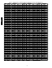
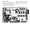
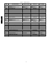
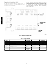
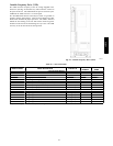
Table 19 — MBB Connections
DISPLAY
NAME
POINT DESCRIPTION SENSOR LOCATION TYPE OF I/O
CONNECTION
PIN NUMBER
INPUTS
Input power from TRAN1 control box 24 VAC J1, 1 --- 3
IGC Fan Request gas section switch input J6, 4
FDWN Fire shutdown switch supply/return/space switch input J6, 6
HUM Space Humidity switch space switch input J7, 4
DigitalScrollUnloader switch input J7, 6
C.ALM Scroll Compressor Alarm switch input J7, 8
CMP.A Compressor A Feedback switch input J7, 10
FIL.S Filter status switch indoor fan section switch input J9 , 2 --- 3
CS.A1 Compressor A1 Current Sensor control box 0---5vdc digital input J 9, 10 --- 12
SPT Space temperature (T55/56) space 10k thermistor J 8, 1 --- 2
SPTO Space temperature offset (T56) space 10k thermistor J 8, 2 --- 3
OAT Outdoor air temperature outdoor coil support 10k thermistor J 8, 5 --- 6
SAT Supply air temperature
indoor fan housing, or
supply duct
10k thermistor J 8, 7 --- 8
SCT.A Saturated condenser temperature, circuit A outdoor coil, circuit A 5k thermistor J8 , 9 --- 10
RAT Return air temperature Return air Section 10k thermistor J8, 13 --- 1 4
FAN.S Fan status switch indoor fan section switch input J 8, 15 --- 1 6
SSP.A Suction pressure, circuit A compressor A suction
0 --- 5 VD C pr ess ur e
transducer
J8 , 18 --- 20
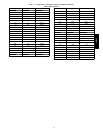
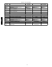
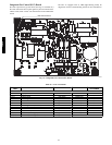
OUTPUTS
CTLR DigitalScrollCtrlPwr relay J10, 11
CCH Crankcase heat relay relay J10, 13
OFC.1 Outdoor fan 1 relay relay J10, 19
IDF Indoor fan VFD pwr relay relay J10, 21
ALRM Alarm relay relay J10, 23
HT.1 Heat Stage 2 relay relay J10, 25
HT.2 Heat Stage 1 relay relay J10, 27
COMMUNICATION
Local Equipment Network (LEN) communication J5 , 1 --- 3
Carrier Comfort Network (CCN) communication J 5, 5 --- 7
Network device power 24 VAC J5, 9 --- 10
Scrolling Marquee Display (LEN) communication J4 , 1 --- 3
Scrolling Marquee Display power 24 VAC J 4, 5 --- 6
Modulation Board (AUX1) LEN communication J3 , 1 --- 3
Optional ECB power 24 VAC J 2, 1 --- 2
48/50PD