


51
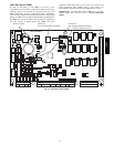
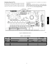
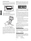
Modulation Board (AUX1)
The AUX1 board controls the compressor capacity and the indoor
fan speed (See Fig. 18 and Table 21.) It outputs a 1--5vdc and a
2--10vdc signal to the DSC and VFD for capacity and fan speed,
respectively. This board is also used as the LEN connection buss
for the ECB, therefore must be operational for the ECB to
communicate.
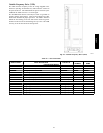
IMPORTANT: The AUX1 board has an 8--po sition DIP switch
(S1) that is factory set for its LEN address. All the switches must
be in the of f position except 4, 5 and 7 which are on (off is towards
the center of the board). Do not change this setting.
C08658
Fig. 18 -- Modulation Board (AUX1)
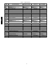
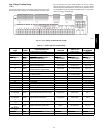
Table 21 — AUX1 Co nnections
DISPLAY
NAME
POINT DESCRIPTION TYPE OF I/O
CONNECTION
PIN NUMBER
OUTPUTS
Input power from TRAN1 24 VAC J 1, 11 --- 1 2
CAPC Compressor Capacity 1 --- 5 vd c CH9
F.SP D Commanded Fan Speed 2 --- 10 vd c CH10
COMMUNICATION
Local Equipment Network (LEN) communication J9 , 1 --- 3
Local Equipment Network (LEN) communication J9 , 1 --- 3
48/50PD