


7
Accessory In stallation
Check to make sure that all accessories including sensors have
been installed and wired as required by the instructions and unit
wiring diagrams.
Orifice Change (48PD Only)
This unit is factory assembled for heating operation using natural
gas at an elevation from sea level to 2000 ft.
Use accessory high altitude kit when installing this unit at an
elevation of 2000 to 7000 ft. For elevations above 7000 ft, refer to
High Altitude section to identify the correct orifice size for the
elevation. Purchase these orifices from your local Carrier dealer.
Follow instructions in accessory Installation Instructions to install
the correct orifices.
Use accessory LP (liquid propane) gas conversion kit when
converting this unit for use with LP fuel usage for elevations up
to 7000 ft. For elevations above 7000 ft, refer to High Altitude
section to identify the correct orifice size for the elevation.
Purchase these orifices from your local Carrier dealer. Follow
instructions in accessory Installation Instructions to install the
correct orifices.
Gas Heat (48PD Only)
Verify gas pressures before turning on heat as follows:
1. Turn off field-supplied manual gas stop, located external to
unit.
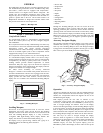
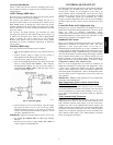
2. Connect pressure gauge to supply gas tap, located on
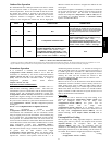
field-supplied manual shutoff valve. (See F ig. 5.)
3. Connect pressure gauge to manifold pressure tap.
4. Turn on field-supplied manual gas stop. Enter Service Test
mode by setting Service Test→TEST to “ON” using the
Scrolling Marquee display . Use the Service Test feature to
set Service Test→HEAT→HT.1 to ON (first stage of heat)
using the Scrolling Marquee.
C06323
Fig. 5 -- Field Gas Piping
5. After the unit has run for several minutes, verify the supply
gas pressure is between 5.5--in. wg to 13.0 --in. wg, and the
manifold pressure is 3.50--in. wg on sizes 03 --14 and 3.00
on size 16. If manifold pressure must be adjusted, refer to
Gas Valve Adjustment section.
IMPORTANT: Supply gas pressure must not exceed 13.0--in. wg.
6. Set Service Test→HEAT→HT.1 to OFF using Scrolling
Marquee.
7. Exit Service Test mode by setting Service Test→TEST to
“OFF” using the Scrolling Marquee.
CONTROLS QUICK SET--UP
The following information will provide a quick guide to setting up
and configuring the 48/50PD series units with ComfortLink™
controls. Unit controls are pre-configured at the factory for
factory-installed options. Field-installed accessories will require
configuration at start-up. Service T est is recommended for initial
start--up. Additionally, specific job requirements may require
changes to default configuration values. See the CCN and Display
parameter tables and other sections of these instructions for more
details.
Control Set Point and Configuration Log
During start up, accessory installation, and equipment service set
points and/or configuration changes might have to be made. When
setting set points or c hanging configuration settings,
documentation is recommended. The Control Log starting on page
106 should be filled out and left with the unit at all times. A copy
should also be provided to the equipment owner.
Standard Unit Control
There are tw o different applications these units can be applied to,
Displacement Ventilation and Single Zone VAV. F or ei th er
application a direct wired space sensor can be used or a
communicating sensor/thermostat can be used. Installation of an
accessory supply air temperature (SAT) sensor in the supply duct is
recommended when using a communication type control. A supply
duct SAT measurement is valid for heating mode display, while the
factory--standard internal SAT is not valid for heating due to its
location upstream of the heating section. When installing the
supply duct SAT, the heating mode display is enabled by setting
Configuration→HEAT→SAT→SAT.H to ENBL.
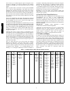
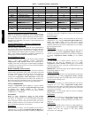
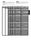
There are several configurations that should be considered for
Displacement Ventilation or Single Zone VAV applications. Table
3 shows these configuration defaults and specific application
settings. These settings typical values and should be adjusted for
each actual specific unit application. Refer to the Operation section
for more detail on these configurations and how they effect the
units operation.
IMPORTANT: M ultiple zoning application is not recommended
at this time with the PD product.
Space Temperature Sensor Control—Direct Wired
(T--55, T--56, or
T--59)
Wire accessory space temperature sensor(s) to the T--55 terminals
on the field connection terminal board located at the unit control
box. No configuration is required when installing a T--55, T--56, or
T--59. Refer to Field-Installed Accessories section for additional
information.
T--58 Communicating Thermostat
Install the T--58 communicating thermostat. Connect the CCN
communication bus from the T--58 to the CCN terminals on the
field connection terminal board located at the unit control box.
Configure the unit’s CCN communication element number, bus
number, and baud rate. Configure the T --58’s CCN communication
bus number and baud rate the same as the unit, while the element
number has to be different. Configure the T --58 to send SPT to the
unit’s element number. Refer to the Field--Installed Accessories
section for additional information.
48/50PD