


100
APPENDIX D -- ADDITIONAL START--UP DATA
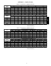
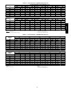
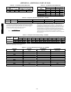
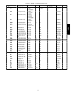
Table 60 — Air Quantity Limits (50PD Units)
UNIT
50PD
COOLING (cfm)
HEATING (cfm)
OPTIONAL ELECTRIC HEAT
05
1200 2000 1200 2000
06
1500 2500 1500 2500
Table 61 — Air Quantity Limits (48PD Units)
UNIT
48PD
COOLING (cfm) HEATING (cfm)
Min Max Min Max
05 (Low Heat)
1200 2000 600 1680
05 (Med Heat)
1200 2000 940 2810
05 (High Heat)
1200 2000 1130 2820
06 (Low Heat)
1500 2500 940 2810
06 (Med Heat)
1500 2500 1130 2820
06 (High Heat)
1500 2500 1510 2520
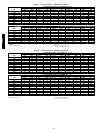
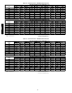
Table 62 — Evaporator Fan Motor Specifications - 48/50PD
48/50PD DRIVE VOLTAGE/PHASE EFFICIENCY MAX BHP MAX AMPS
05 & 06 Low & High
208/230---3ph 0.80 2.0 6.4
460---3ph 0.80 2.0 3.2
NOTES:
1. Extensive motor and electrical testing ensures that the motors can be utilized
with confidenceup to the maximum applied bhp,watts, and amps. Using the fan
motor up to the maximum ratings shown will notresult in nuisance tripping or
premature motor failure. Unit warranty willnot be affected.
2. Convert bhp to watts using the following formula:
watts =
bhp (746)
motor efficiency
3. The EPACT (Energy Policy Actof 1992) regulatesenergy requirements for
specific types of indoor-fan motors. Motorsregulated by EPACT include any
general purpose, T-frame (three-digit, 143 and larg er), single-speed, foot
mounted,polyphase, squirrel cage induction motors of NEMA (NationalElectrical
Manufacturers Association) design A and B, manufactured for use in the United
States.Ranging from 1 to 200 Hp,these continuous-duty motors operate on 230
and 460 volt, 60Hz power. If a motor doesnot fit into these specifications, the
motor does not have to be replaced by an EPACT-compliant energy-efficient motor.
Variable-speed motors are exemptfro m EPACT compliance requirements.
Therefore,the indoor-fan motorsfor Carrier 48/50PG03--14 units are exempt from
these requirements.
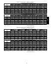
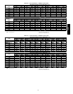
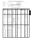
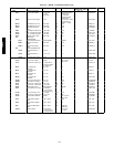
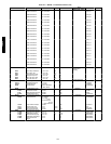
Table 63 — Fan Rpm at Motor Pulley Settings* - 48/50PD
UNIT
48/50PD
DRIVE
MOTOR PULLEY TURNS OPEN
0
1
/
2
1 1
1
/
2
2 2
1
/
2
3 3
1
/
2
4 4
1
/
2
5
05
Low 910 878 847 815 784 753 721 690 659 627 596
High 1173 1139 1104 1070 1035 1001 966 932 897 863 828
06
Low 978 949 920 891 863 834 805 776 748 719 690
High 1261 1227 1194 1161 1128 1095 1062 1028 995 962 929
*Approximate fan rpm shown, based on 1725 rpm motor.
NOTE: Factory speed setting is at 5 turns open.
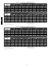
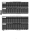
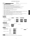
Table 64 — Accessory/FIOP Pressure Drop (in. wg) - 48/50PD
AIRFLOW
(CFM)
ELECTRIC
HEAT
ECONOMIZER
(Vertical)
ECONOMIZER
(Horizontal)
600
0.01 0.01 0.03
800
0.01 0.01 0.05
1000
0.02 0.02 0.07
1200
0.02 0.03 0.10
1400
0.03 0.04 0.14
1600
0.04 0.06 0.17
1800
0.05 0.07 0.22
2000
0.07 0.09 0.26
2200
0.08 0.11 0.31
2400
0.10 0.13 0.37
2600
0.11 0.15 0.43
2800
0.13 0.18 0.49
3000
0.15 0.21 0.56
48/50PD