


81
APPENDIX B - VFD INFORMATION
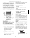
On 48/50PD units, the supply fan speed is controlled by a 3--phase
VFD. The VFD is located in the supply fan section behin d an
indoor fan scroll. The VFD speed is controlled directly by the
ComfortLinkt controls through a 0--10Vdc signal based on a
space temperature sensor. The VFD has a display, which can be
used for service diagnostics, but setup of the control is to be done
through the scrolling marquee display .
The VFD is powered during normal operation to prevent
condensation from forming on the boards during the off mode and
is stopped by driving the speed to 0 (by sending a 0Vdc signal to
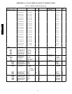
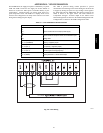
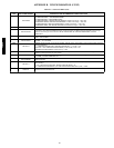
the VFD). The units use ABB VFDs. The interface wiring for the
VFDs is shown in the figure below. The VFD connects to
ComfortLink through a 0--10Vdc output on the AUX1 board.
Terminal designations are shown in the Terminal Designation table.
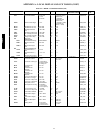
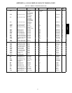
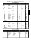
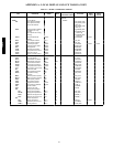
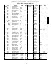
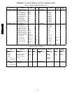
Configurations are shown in the VFD Configurations table.
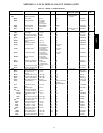
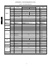
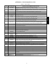
Table 39 — VFD TERMINAL DESIGNATIONS
TERMINAL FUNCTION
U1
V1
W1 Three---Phase main circuit input power supply
U2
V2 Three---Phase AC output to motor, 0V to maximum input
W2 voltage level
X1 --- 1 1 (G ND )
X1 --- 1 2 (C OMM ON) Factory---supplied jumper
X1---10 (24VDC)
X1 --- 1 3 (D I --- 1) Run (factory---supplied jumper)
X1---10 (24VDC) Start Enable 1 (factory---supplied jumper). When opened,
X1 --- 1 6 (D I --- 4) the drive goes to emergency stop
X1 --- 2 (AI --- 1 )
X1 --- 3 (AG ND ) Factory wired for 0---10Vdc remote input
A48-7712
0-10Vdc
C08674
Fig. 40 -- VFD Wiring
48/50PD