


53
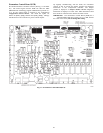
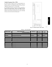
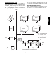
Variable Frequency Drive (VFD)
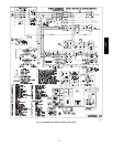
The VFD varies the frequency of the AC voltage supplied to the
indoor fan. (See Fig. 20 an d Table 23.) This causes the variance in
the speed of the fan. The commanded fan speed is received by the
VFD from the AUX1 board as a 2--10vdc signal.
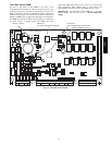
The AI1 DIP switch must be in the off (or towards “ U”) position to
properly read the analog signal. There are three jumper wires that
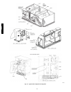
must remain installed for proper operation. The VFD is mounted
behind the fan housing on the fan sled and the remote keypad is
mounted on the front of the fan housing for easy access. The VFD
is factory set to the auto mode for unit operation.
C09146
Fig. 20 -- Variable Frequency Drive (VFD)
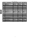
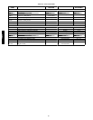
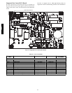
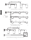
Table 2 3 — VFD Connections
DISPLAY NAME POINT DESCRIPTION TYPE OF I/O
TERMINAL
NUMBER
TERMINAL
NAME
LOW VOLTAGE INPUTS
Shielded Cable Ground Shield 1 SCR
F.SP D Commanded Fan Speed 2 --- 10v dc 2 AI1*
Analog Input 1 Common Ground 3 AGND
Low Voltage Power (jumped to DI1 & DI4) 24v 10 24v
Low Voltage Common (jumped to DCOM) Ground 11 GND
Discrete Inputs Common (jumped from GND) Ground 12 DCOM
Discrete Input 1 (jumped from 24v) Switch Input 13 DI1
Discrete Input 4 (jumped from 24v) Switch Input 16 DI4
HIGH VOLTAGE
Vo lta ge Le g fr om IF C --- 21 Voltage Input U1 MAINS
Vo lta ge Le g fr om IF C --- 22 Voltage Input V1 MAINS
Vo lta ge Le g fr om IF C --- 23 Voltage Input W1 MAINS
Vo lta ge Le g to IF M --- 3 Voltage Output U2 MOTOR
Vo lta ge Le g to IF M --- 2 Voltage Output V2 MOTOR
Vo lta ge Le g to IF M --- 1 Voltage Output W2 MOTOR
* Requires the Al1 dip switch to be in in the Off (or towards“U”) position.
48/50PD