


31
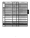
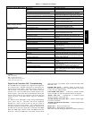
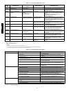
Table 9 — Cooling Service Analysis
PROBLEM CAUSE REMEDY
Compressor and Fan Will Not Start Power failure. Call power company.
Fuse blown or circuit breaker tripped. Check CB1 and
CB2.
Replace fuse or reset circuit breaker.
Disconnect off. Power disconnect.
Compressor time guard to prevent short cycling. Check time guards using ComfortLinkt Scrolling
Marquee also the DSC has a 2 minute anti---short time
Occupancy schedule set point or supply set point not
calling for Cooling.
Check cooling demand using ComfortLink Scrolling
Marquee.
Outdoor temperature too low. Check Compressor Lockout Temperature using
ComfortLink Scrolling Marquee.
Active alarm. Check active alarms using ComfortLink Scrolling
Marquee and DSC alert flash codes
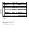
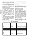
CompressorCycles(otherthan
normally satisfying demand).
Insufficient line voltage. Determine cause and correct.
Active alarm. Check active alarms using ComfortLink Scrolling
Marquee and DSC alert flash codes
Compressor Operates
Continuously.
Unit undersized for load. Decrease load or increase size of unit.
Occupancy schedule set point or supply set point too
low. Compressor running at lowest capacity
Check and adjust set points if needed.
Compressor contactor stuck on Check cooling demand using ComfortLink Scrolling
Marquee and DSC alert flash codes.
Dirty air filters. Replace filters.
Low refrigerant charge. Check pressure, locate leak, repair, evacuate, and
recharge.
Condenser coil dirty or restricted. Clean coil or remove restriction.
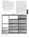
Excessive Condenser Pressures. Loose condenser thermistors. Tighten thermistors.
Dirty condenser coil. Clean coil.
Refrigerant overcharge. Recover excess refrigerant.
Faulty TXV.
1.Check TXV bulb mounting and secure tightly to suction
line and insulate.
2.Replace TXV (and filter drier) if stuck open or closed.
Condenser air restricted or air short cycling. Determine cause and correct.
Restrictioninliquidtube. Remove restriction.
Condenser Fans Not Operating. No Power to contactors. Fuse blown or plug at motor loose.
Excessive Suction Pressure. High heat load. Check for sources and eliminate
Faulty TXV.
1.Check TXV bulb mounting and secure tightly to suction
line and insulate.
2.Replace TXV (and filter drier) if stuck open or closed.
Refrigerant overcharged. Recover excess refrigerant.
Suction Pressure Too Low. Dirty air filters. Replace air filters.
Low refrigerant charge. Check pressure, locate leak, repair, evacuate, and
recharge.
Faulty TXV.
1.Check TXV bulb mounting and secure tightly to suction
line and insulate.
2.Replace TXV (and filter drier) if stuck open or closed.
Insufficient evaporator airflow. Check belt tension. Check for other restrictions.
Indoor Fan Running to slow or off while compressor is
on
Check VFD display is illuminated and shows Auto
mode. Power supplied to VFD. Check 0---10vdc signal
present at AUX1 board.
Temperature too low in conditioned area (low
return---air temperature).
Reset thermostat or occupancy schedule.
LEGEND
CB -- Circuit Breaker
DSC -- Digital Scroll Controller
TXV -- Thermostatic Expansion Valve
VFD -- Variable Frequency Drive
Digital S croll Controller (DSC) Troubleshooting
The 48/50PD units are equipped with a digital scroll compressor.
The compressor has a solenoid unloader that is controlled by the
digital scroll controller (DSC). This DSC turns the unloader on
and off within a 20 second window. The amount of time the
unloader is on verses off within that 20 seconds depends on the
desired capacity. This means that the ComfortLink control does
not have direct control of the compressor, but it does however
control the power to the DSC and the signal for commanded
capacity.
The DSC has three LED lights to help during troubleshooting;
green, yellow, and red The DSC will run the compressor
unloaded for a half a second on start up and one second on
shutdown to prevent reverse rotation. A two minute anti --short
time guard is applied by the DSC after shutting the compressor off.
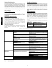
The DSC has an alarm relay output that is connected to the MBB.
When this MBB input switch is closed, the MBB activ ates the
T051 alert. Check the LED status on the DSC for flash alarm
codes and correct any problems. Table 10 shows the DSC’s Red
LED flash codes.
POWER LED (green) ⎯ indicates voltage is present at the
24VAC power terminal. When the 2 minute anti--short cycle timer
is active, the green LED will flash.
UNLOADED LED (yellow) ⎯ indicates the unloader solenoid
status. The LED is on when the unloader solenoid is energized.
ALERT LED (red) ⎯ communicates an abnormal system
condition through a unique flash code.
All LEDs Flashing at the Same Rate ⎯ indicates 24VAC supply
is too low for operation.
All LEDs On Solid at the Same Time ⎯ indicates Digital Scroll
Controller failure.
Flash Code 1 ⎯ Reserved for future use
Flash Code 2 ⎯ High Discharge Temperature
This occurs when the discharge temperature thermistor (DTT) has
48/50PD