


14
(Configuration→CCN→SCH.O→OV.SP) is set to YES.
The length of the override period is determined by the
Timed Override Hours setting
(Configuration→CCN→SCH.O→OV>EX).
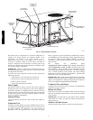
Compr essor Operation
The 48/50 PD units use a Copeland Digital Scroll Compressor that
can vary the refrigerant capacity between 100 and 15%. This is
accomplished by a mechanism in the compressor that separates the
two scroll spirals which stops the pumping of the refrigerant gas.
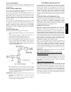
This mechanism is operated by the differential pressure between
the suction and discharge of the compressor. The pressure to
operate the unloading mechanism is controlled by a small solenoid
situated in a refrigerant line between the top of the compressor and
the suction line. When the solenoid is energized the compressor is
unloaded. The solenoid coil is controlled by the Copeland Digital
Scroll Controller (DSC) that operates on a 1 to 5V signal from the
ComfortLink Auxiliary Board (AUX1) and converts this into a
Pulse Width Modulated (PWM) signal to the solenoid valve. The
pulse width modulated signal is an on and off signal that repeats
every 15 seconds with the off time portion of the 15 seconds
representing the % loading of the compressor.
The C ompressor Capacity (Outputs→COOL→CAPC) can be
monitored on the ComfortLink Scrolling Marquee Display. The
Compressor Capacity value is determined by a Proportional,
Integral, Derivative (PID) algorithm that controls the Supply Air
Temperature (T emperatures→AIR.T→SAT) to the Supply Air
Control Point (Run Status→COOL→SA.CP).
The Compressor Minimum Capacity
(Configuration→COOL→MIN.C) is configured at the factory to
70%. This is the minimum compressor capacity that gives the
highest SEER rating for a 48 series unit with the highest gas heat
option and no economizer per AHRI standard 210/240. Since the
AHRI rating standard does not account for energy savings that can
be realized by displacement ventilation a ir distribution system and
extending economizer cooling operation at higher supply air
temperature set points, a complete energy analysis should be
conducted before changing the Compressor Minimum Capacity
(Configuration→COOL→MIN.C) setting to determine the energy
savings at a lower Compressor Minimum Capacity
(Configuration→COOL→MIN.C) setting.
Indoor Fan Operation
The indoor fan is controlled by the Indoor Fan VFD Power Relay
(Outputs→FANS→IDF) on the MBB (main base board) control,
which then operates the indoor fan contactor (IFC). On the
48/50PD units the Indoor Fan VFD Power Relay
(Outputs→FANS→IDF) is always on so that power is supplied to
the VFD electronic boards. This prevents the formation of
condensation on the VFD electronic boards and provides power to
the remote VFD display so that error codes and VFD configuration
parameters can be verified.
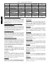
The 48/50PD unit controls require an accurate supply duct CFM at
the unit design point where the indoor fan will run at the Supply
Fan Maximum Speed (Configuration→UNIT→FS.MX).The
Supply Fan Maximum Speed (Configuration→UNIT→FS.MX)
is used for operation of the economizer and power exhaust. The
supply duct CFM is configured by the Indoor Fan Max Speed
CFM (Configuration→ECON→IDF.C). Default values for
Indoor Fan Max Speed CFM (Configuration→ECON→IDF.C)
are at 400 CFM per ton or 1600 CFM for the 05 size and 2000
CFM for the 06 size. It is preferred to use the supply duct CFM
from an air balance report to configure the Indoor Fan Max Speed
CFM (Configuration→ECON→IDF.C). If an air balance report
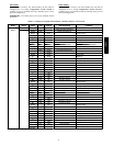
is not available then use the fan tables supplied in this book to
determine Fan Max Speed CFM
(Configuration→ECON→IDF.C). When using the fan tables to
determine Fan Max Speed CFM
(Configuration→ECON→IDF.C) set Economizer Position T est
(Service Test→INDP→ECON) to 0 (Economizer Damper Closed)
and Indoor Fan Speed Test (Service Tes→FANS→F.S PD) equal to
(Configuration→UNIT→FS.MX). Measure the supply to return
duct static pressure difference and indoor fan RPM. Make
correction to static pressure for all options installed in the unit per
the accessory pressure drop table. Determine I ndoor Fan Max
Speed CFM (Configuration→ECON→IDF.C)
on the fan table
where the corrected static pressure and RPM cross.
The supply fan speed range is configured by the Supply Fan
Maximum Speed (Configuration→UNIT→FS.MX) and the
Supply Fan Minimum Speed (Configuration→UNIT→FS.MN).
These configuration values are in units of % speed referenced to a
2 to 10VDC signal to the VFD AI1 input with 2VDC representing
0% speed and 10VDC representing 100% speed or 0 to 60HZ
VFD frequency output to the motor.
The Supply Fan Minimum Speed
(Configuration→UNIT→FS.MN) can be user configured
between 10 and 70%. The Supply Fan Minimum Speed default
value is 70%, this provides the greatest energy efficiency rating for
a unit without an economizer in a mixed air type duct application.
The Supply Fan Maximum Speed
(Configuration→UNIT→FS.MX) can be configured between 80
and 100%. The Supply Fan Maximum Speed default value is
100%. Set the indoor fan pulley to the application design point
CFM for heating and cooling at 100% fan speed so that the CFM is
not lower than the minimum CFM allowed in the product data. If
the exact CFM can not be set by the half turn pulley settings then
adjust the Supply Fan Maximum Speed
(Configuration→UNIT→FS.MX) to fine tune the CFM to the
application requirements. The Supply Fan Maximum Speed
(Configuration→UNIT→FS.MX) RPM must now produce
supply CFM that is not lower that the minimum CFM allowed in
the product data for heating and cooling.
The indoor fan may operate during cooling with compressors
mode, free cooling with outdoor air mode, heating mode, or for
ventilation with outdoor air mode.
The indoor fan operation can be affected by the following:
S FanOnWhenOccupied(Configuration→UNIT→OC.FN)
S IAQ Analog Fan Config (Configuration→AIR.Q→IA.FN)
S IAQ Switch Fan Config (Configuration→AIR.Q→II.FN)
S Fan Status Switch (Configuration→UNIT→FN.SW)
When the unit is in occupied or unoccupied cooling mode the
supply fan will modulate to maintain the space temperature sensor
set point between the configured Supply Fan Maximum Speed
(Configuration→UNIT→FS.MX) and the Supply Fan Minimum
Speed (Configuration
→UNIT→FS.MN).
When the 40PD or 50 PD unit is in occupied or unoccupied
heating mode (gas heat or electric heat mode) the indoor fan will
operate at the Supply Fan Maximum Speed
(Configuration→UNIT→FS.MX) setting.
For 48PD gas heating units, the IGC control fan output is also
monitored by the MBB control. This can result in additional
modifications of fan delays or other operation due to safety
functions of the IGC control.
When the PD unit is in free cooling mode the indoor fan will
modulate to maintain The Occupied Cool Set Point
(Setpoints→OCSP), the Unoccupied Cool Set Point
(Setpoints→UCSP), Occupied Heat Set Point
(Setpoints→OHSP), or the Unoccupied Heat Set Point
(Setpoints→UHSP).
When the PD unit is in ventilation mode and Fan On When
Occupied (Configuration→UNIT→OC.FN) the indoor fan will
operate at the Vent Mode Fan Speed
(Configuration→UNIT→FS.VM). Vent Mode Fan Speed
(Configuration→UNIT→FS.VM) factory default is 50% and can
be user configured between 40 and 100%.
48/50PD