


64
C08570
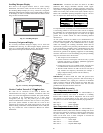
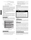
Fig. 33 -- Condenser--Fan Adjustment
Verify Sensor Performance
Verify that thermistor, transducer, and switch inputs are reading
correctly. These values can be accessed through the Scrolling
Marquee display in the Temperatures, Pressures, and Inputs menus.
Some values will depend on configuration choices. Refer to the
Control Set Up Checklist completed for the specific unit
installation and to the configuration tables in Appendix A.
Economizer Operation During Power Failure
Dampers have a spring return. In event of power failure, dampers
will return to fully closed position until power is restored. Do not
manually operate damper motor.
Evacuation
Proper evacuation of the system will remove noncondensables and
ensure a tight, dry system before charging. Evacuate from both
high and low side ports. Never use the system compressor as a
vacuum pump. Refrigerant tubes and indoor coil should be
evacuated to 500 microns. Always break a vacuum with dry
nitrogen. The two possible methods are the deep vacuum method
and the triple evacuation method.
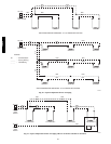
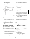
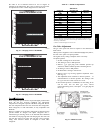
Deep Vacuum Method
The deep vacuum method requires a vacuum pump capable of
pulling a minimum vacuum of 500 microns and a vacuum gauge
capable of accurately measuring this vacuum depth. The deep
vacuum method is the most positive way of assuring a system is
free of air and liquid water. (See Fig. 34.)
LEAK IN
SYSTEM
VACUUM TIGH
T
TOO WET
TIGHT
DRY SYSTEM
0
1
2
3
4
56
7
MINUTES
5000
4500
4000
3500
3000
2500
2000
1500
1000
500
MICRONS
C06264
Fig. 34 -- Deep Vacuum Graph
Triple Evacuation Method
The triple evacuation method should only be used when vacuum
pump is capable of pumping down to 28--in. of mercury and
system does not contain any liquid water. Proceed as follows:
1. Pump system down to 28--in. of mercury and allow pump
to continue operating for an additional 15 minutes.
2. Close service valves and shut off vacuum pump.
3. Connect a nitrogen cylinder and regulator to system and
open until system pressure is 2 psig.
4. Close service valve and allow system to stand for 1 hr.
During this time, dry nitrogen will be able to diffuse
throughout the system, absorbing moisture.
5. Repeat this procedure. System will then contain minimal
amounts of contaminants and water vapor.
Refrigerant Charge
Amount of refrigerant charge is listed on unit nameplate. Refer to
Carrier GTAC II; Module 5; Charging, Recovery, Recycling, and
Reclamation section for charging methods and procedures. Unit
panels must be in place when unit is operating during charging
procedure.
Puron® (R-410A) refrigerant systems should be charged with
liquid refrigerant. Use a commercial type metering device in the
manifold hose.
UNIT OPERATION AND SAFETY HAZARD
Failure to follow this warning could cause personal
injury, death and/or equipment damage.
Puron (R--410A) refrigerant systems operate at higher
pressures than standard R--22 systems. Do not use R--22
service equipment or components on Puron refrigerant
equipment. Gauge set, hoses, and recovery system must
be designed to handle Puron refrigerant. If unsure
about equipment, consult the equipment manufacturer.
!
WARNING
IMPORTANT: Do not use recycled refrigerant as it may contain
contaminants.
No Charge in the System
Use standard evacuating techniques. After evacuating system,
weigh in the specified amount of refrigerant (refer to unit
nameplate). Verify charge using the charging chart via “Charge in
the System.”
Charge in the System
IMPORTANT: The circuit must be running in normal cooling
mode with the compressor capacity at 100%. The VFD must be
running at max fan speed and indoor airflow must be within
specified air quantity limits for cooling (See Appendix D). All
outdoor fans must be on and running at high speed. Use the
Cooling Service Test Outdoor Fan Override function to start all
outdoor fans.
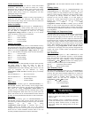
An accurate pressure gauge and temperature--sensing device is
required. Charging is accomplished by ensuring the proper amount
of liquid subcooling. Connect pressure gauge to the compressor
discharge service valve. Connect temperature sensing device to the
liquid line between the condenser and the TXV (thermostatic
expansion valve), and insulate it so that ambient temperature does
not affect reading. Use the cooling charging chart (Fig. 35--36) to
determine if additional charge is needed or if some charge needs to
be removed from the system.
To Use the Cooling Charging Chart
Use the temperature and pressure readings, and find the
intersection point on the cooling charging chart. If intersection
point on chart is above line, add refrigerant. If intersection point on
chart is below line, carefully recover some of t he charge. Recheck
suction pressure as charge is adjusted.
48/50PD