


15
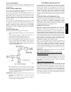
Outdoor Fan Operation
The 48/50 PD units use a multi--speed outdoor fan motor to control
the head pressure within an acceptable range at low outdoor
ambient temperatures. On the 48 and 50 PD --05 and 06 size units
the outdoor fan contactor is powered on the load side of the
compressor contactor so the outdoor fans will run only when the
compressor contactor is energized. When the outdoor fan
contactor is not energized the outdoor fan runs at high speed.
When the outdoor fan contactor is energized the outdoor fan runs
at low speed.
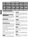
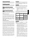
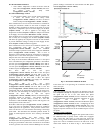
The outdoor fan speed is controlled by a system three of fan levels
set up in the control software. Table 6 shows the three levels and
fan speeds for each level. The fan levels are determined by
Outdoor Air Temperature (Temperatures→AIR.T→OAT) but can
be overridden by Condenser Pressure A (Pressures→SCP.A)
inputs to the Main Base Board.
FAN
LEVEL
FAN
SPEED
CONDITIONS TO TRANSITION TO NEXT
LOWER LEVEL
CONDITIONS TO TRANSITION TO NEXT
HIGHER LEVEL
0 OFF N/A
1. Compressor Contactor is ON
(on initial start up outdoor fan runs at Level 2 for
10 seconds before moving to correct level based
on outside air temperature or Condenser Pres-
sure A)
1 LOW 1. Compressor Contactor is OFF
1. Outside Air Temperature Control — Fan
Lev2 On Temperature 55 F or above (Configu-
ration→COOL→OFC→2.ON >=55F)*
2. Condenser Pressure A Override — Fan
Lev1 Max Pressure 450 psig or above (Config-
uration→COOL→OFC→1.MXP>= 450 psig)*
2 HIGH
1 . O ut si de A ir Te mp er a tu r e C on tr o l --- --- Fa n
Lev2 Off Temperature 45 F or below (Confi-
guration→COOL→OFC→2.OFF <=45F)*
2. Condenser Pressure A Override --- --- Fan
Lev2 Min Pressure 200 psig or below (Config-
uration→COOL→OFC→2.MNP<= 200 psig)*
N/A
Table 6 — Fan Level Control of Outdoor Fan
*Configuration parameters 1.MXP, 2.MNP,2.ON and 2.OFFfactory default configuration should not be changed. The defaultconfigurationshave been qualified over a wide
range of conditio ns and are prov ided in case a field r e placement o f th e control board occurs and the settings need to be checked or manually configured.\
Economizer Operation
If an economizer is installed, then Economizer Installed
(Configuration→UNIT→EC.EN) should be set to YES. The
economizer is controlled by the Econo Commanded Position
(Outputs→ECON→EC.CP) on the Economizer Control Board
(ECB). Feed back from the economizer actuator is output on
configuration parameter Econo Actual Position
(Outputs→ECON→EC.AP).
Economizer Actuator
Communication
The economizer actuator used with the 48/50PD units is a
Multi--Function Technology (MFT) actuator. This allows the
ComfortLink system to communicate with the actuator through a
feedback signal. The configuration Economizer Contro l Type
(Configuration→ECON→E.CTL) determines the communication
method, either digital or analog, used to communicate between the
Economizer Control Board and the economizer actuator.
The power to the unit must be cycled after the Economizer Control
Type (Configuration →ECON→E.CTL) configuration parameter
is changed.
E.CTL = 1 or 2 (Digital/Position or Digital/Command)
When Economizer Control Type
(Configuration→ECON→E.CTL) is set to 1, the Economizer
Control Board will communicate with the economizer actuator
using the digital protocol, from Economizer Control Board plug
J7--1 to actuator pin 5. The commanded position and the actuators
actual position are communicated back and forth between the
actuator and the Economizer Control Board. When the Economizer
Control Board and actuator first initiate communication, a Control
Angle Economizer Control Type (Operating Modes→
ECON→C.ANG) is provided to the Economizer Control Board
and defines the actuator’s range of motion. The control angle must
be greater than the Min Actuator Ctrl Angle
(Configuration→ECON→M.ANG). During this digital control,
the Economizer Control Board analog 4 to 20 mA output will
represent the actuator’s actual position when E.CTL = 1 or
commanded position when E.CTL = 2. Because the wiring has a
built --in 500--ohm resistor, the 4 to 20mA signal is converted to a 2
to 10VDC signal that is accessible via a field connected terminal
board TB--8 and TB--9. However, before this signal can be read
remotely, the violet wire that connects the actuator to field
connection terminal board TB--J10-- 8 must be removed or cut.
E.CTL = 3 (Analog Control)
When E.CTL is set to 3, the Economizer Control Board will NOT
communicate with the economizer actuator directly with the 4 to
20mA analog signal wired to TB--8 and TB--9 along with the
500--ohm resistor producing a 2 to 10VDC signal for the actuator.
While in this mode, the actuator’s built--in 2 to 10VDC feedback
signal s accessible via TB--9 and TB--10 any time because it is not
used by the Economizer Control Board.
Free
Cooling
The economizer will be allowed to help with cooling if the
Outdoor Air Temperature (Temperatures→AIR.T→OAT) is less
than the configured Econo Cool Hi Temp Limit
(Configuration→ECON→EH.LO) and greater than the
configured Econo Cool Lo Temp Limit
(Configuration→ECON→EL.LO). If an enthalpy sensor is
installed, the outdoor temperature must be below the Econo Cool
Hi Temp Limit (Configuration→ECON→EH.LO) and the
Outdoor Enthalpy Switch (Inputs→GEN.I→ENTH) must be
LOW.
Unoccupied Fr ee Cooling
The unoccupied free cooling algorithm attempts to maintain the
building space half way between the Occupied Cool Set Point
(Setpoints→OCSP) and O ccupied Heat Set Point
(Setpoints→OHSP) using only the economizer when the
conditions in the building and the outdoors are suitable., during
UNoccupied periods if the air in the building and the outdoor air
are suitable. Three different configurations define this algorithm:
1. Unoccupied Free Cooling
(Configuration→ECON→UEFC)
48/50PD