


37
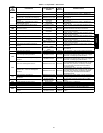
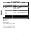
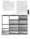
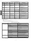
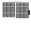
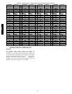
Thermistor Troubleshooting
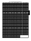
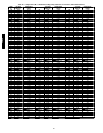
The electronic control uses thermistors to sense temperatures used
to control operation of the unit. Resistances at various temperatures
are listed in Table 15--17. Thermistor pin connection points are
shown in the Major System Components section. The general
locations of the thermistors are shown the Major System
Components section.
Air Temperatures
Air temperatures are measured with 10 kilo-ohm thermistors. This
includes supply-air temperature (SAT), outdoor-air temperature
(OAT), space temperature sensors (T55, T56, T58), and return air
temperature (RAT).
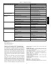
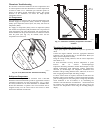
The supply air temperature (SAT), return air temperature (RAT)
and outdoor air temperature (OAT) thermistors use a snap-mount to
attach through the unit sheet metal panels. The snap-mount tabs
must be flattened on the tip end of the sensor to release for removal
from the panel. (See Fig. 10.) To reinstall, make sure the
snap-mount tabs extend out.
C07015
Fig. 10 -- SAT, RAT and OAT Thermistor Mounting
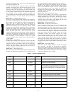
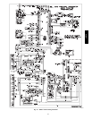
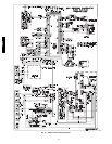
Refrigerant Temperatures
Condenser coil temperatures are measured with 5 kilo-ohm
thermistors. These measurements provide an approximate saturated
condensing temperature for each circuit (SCT.A). Fig. 11 shows
the factory locations for the SCT thermistors on 48/50PD units.
Ensure that thermistors are placed at the correct location and are
snapped securely over the return bend so that contact is made
between the thermistor and the tube.
C07016
Fig. 11 -- Saturated Condensing Temperature Thermistor
Location
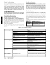
Thermistor/Temperature Sensor Check
A high quality digital volt-ohmmeter is required to perform this
check.
Connect the digital voltmeter across the appropriate thermistor
terminals at the J8 terminal strip on the Main Base Board (see
Major System Components section).
Using the voltage reading obtained, read the sensor temperature
from Table 15--17.
To check thermistor accuracy, measure t emperature at probe
location with an accurate thermocouple-type
temperature-measuring instrument. Insulate thermocouple to avoid
ambient temperatures from influencing reading. Temperature
measured by thermocouple and temperature determined from
thermistor voltage reading should be close, within 5°F , if care was
taken in applying thermocouple and taking readings.
If a more accurate check is required, unit must be s hut down a nd
thermistor removed and checked at a known temperature (freezing
point or boiling point of water) using either voltage drop measured
across thermistor at the J8 terminal, or by determining the
resistance with unit shut down and thermistor disconnected from
J8. Compare the values determined with the value read by the
control in the Temperatures mode using the Scrolling Marquee
display.
48/50PD