


62
To inspect blower wheel, open heat section door. Using a
flashlight, look into the flue exhaust duct to inspect. If cleaning is
required, remove motor and wheel assembly by removing the
screws holding the flue box cover to the flue box. Remove the
screws holding the inducer housing to the inlet plate. The wheel
can then be removed from the motor shaft and cleaned with a
detergent or solvent. Replace the wheel onto the motor shaft in the
correct position and reassemble the flue cover onto the flue box.
Lubrication
Compressors
Each compressor is charged with the correct amount of oil at the
factory.
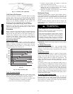
UNIT DAMAGE HAZARD
Failure to follow this caution may result in damage to unit
components.
The compressor is in a Puron refrigerant system and uses a
polyolester (POE) oil. This oil is extremely hygroscopic,
meaning it absorbs water readily. POE oils can absorb 15
times as much water as other oils designed for HCFC and
CFC refrigerants. Avoid exposure of the oil to the
atmosphere.
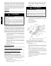
CAUTION
!
Polyolester (POE) compressor lubricants are known to cause long
term damage to some synthetic roofing materials. Exposure, even if
immediately cleaned up, may cause roofing materials to become
brittle (leading to cracking) within a year. When performing any
service which may risk exposure of compressor oil to the roof, take
appropriate precautions to protect roofing. Procedures which risk
oil leakage include compressor replacement, repairing refrigerant
leaks, and replacing refrigerant components. To prepare rooftop:
1. Cover extended roof work area with an impermeable plastic
dropcloth or tarp. Make sure a 10 x 10 ft area around the
work area is covered.
2. Cover area in front of the unit service panel with a terry
cloth shop towel to absorb lubricant spills and prevent
run-offs. Towel will also protect dropcloth from tears caused
by tools or components.
3. Place terry cloth shop towel inside the unit directly under
components to be serviced to prevent spills through the
bottom of the unit.
4. Perform the required service.
5. Remove an dispose of any oil contaminated material per
local codes.
Indoor Fan Shaft Bearings
The indoor fan has permanently sealed bearings. No field
lubrication is necessary.
Condenser and Evaporator--Fan Motor Bearings
The condenser-fan and evaporator-fan motors have permanently
sealed bearings, so no field lubrication is necessary .
Economizer o r Manual Outside Ai r Damper
If blade adjustment is required, refer to unit or accessory
installation instructions.
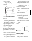
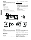
Evaporator Fan Service and Replacement
The units feature a slide-out fan deck for easy servicing of the
indoor-fan motor, pulleys, belt, bearings and VFD. To service
components in this section, perform the following procedure:
1. Turn off unit power.
2. Open the fan section access door.
3. Remove two no. 10 screws at front of slide-out fan deck.
Save screws. (See Fig. 30.)
4. Disconnect the electrical wires connected to the slide--out
fan deck (supply air thermistor and fan status switch if
installed). Wires may be damaged if not disconnected.
5. Fan deck can now be slid out to access serviceable
components.
UNIT DAMAGE HAZARD
Failure to follow this caution may result in damage to the
unit.
DO NOT SLIDE FAN DECK OUT PAST THE FAN
DECK STOP. If further access is required, the fan deck
must be supported. Make sure plugs and wiring are not
pinched between fan housing and unit sheet metal post.
CAUTION
!
6. To replace fan deck to operating position, slide fan deck
back into the unit. Secure with the two no. 10 screws
removedinStep3.
7. Re-attach electrical wires.
8. Close fan section access door.
9. Restore power to unit.
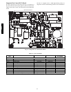
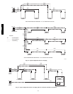
C08661
Fig. 30 -- Evaporator--Fan Motor Adjustment
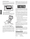
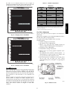
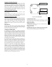
Evaporator Fan Performance Adjustment
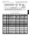
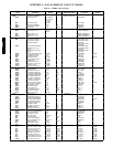
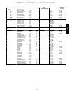
Fan motor pulleys are factory set for speed shown in Appendix D.
To change fan speeds:
1. Shut off unit power supply.
2. Loosen nuts on the 4 carriage bolts in the mounting base.
Using adjusting bolts and plate, slide motor and remove
belt.
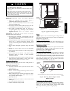
3. Loosen movable-pulley flange setscrew. (See Fig. 31.)
4. Screw movable flange toward fixed flange to increase speed
and away from fixed flange to decrease speed. Increasing
fan speed increases load on motor. Do not exceed maximum
speed specified in Appendix D.
See Appendix D for air quantity limits.
5. Set movable flange at nearest keyway of pulley hub and
tighten setscrew. (See Appendix D for speed change for
each full turn of pulley flange.)
6. Replace belts.
48/50PD