


SMOKE CONTROL — When the 39L or 39NX unit is
equipped with an optional smoke control and a fire system
is installed, 4 modes are provided to control smoke within
areas serviced by the air-handling unit. Each mode must be
energized individually from the approved building fire alarm
system, and the corresponding alarm is then generated at the
local interface device or Building Supervisor.
The system must include a separate return fan and an ex-
haust air damper witha4to20mAactuator.
The building fire alarm system must provide 4 normally-
open dry contact closures and a double-pole, double-throw
(DPDT) relay (24 vac coil, contacts rated 10 amps at
240 vac) for the Fire Shutdown mode.
Fire Shutdown Mode — The fire alarm system must provide
a normally-open dry contact closure which, when activated,
energizes the Fire Shutdown mode.
When the Fire Shutdown mode is energized, the supply
and return fans stop, the outside and exhaust air dampers
close, and the return-air dampers open.
This mode remains in effect as long as the input signal is
maintained at the fire system panel. An alarm is generated
from this input and sent to the Building Supervisor. In order
for this mode to be initiated, the input signal must be main-
tained for no less than 2 seconds.
Evacuation Mode — The building fire alarm system must pro-
vide a normally-open dry contact closure which, when ac-
tivated, energizes the Evacuation mode. When the
Evacuation mode is energized, the supply fan shuts down,
the return fan starts, the outside-air and return-air dampers
close, and the exhaust air dampers open.
This mode remains in effect for as long as the input signal
is maintained at the fire system panel. An alarm is generated
from this input and sent to the Building Supervisor. In order
for this mode to be initiated, the input signal must be main-
tained for no less than 2 seconds.
Pressurization Mode — The building fire alarm system must
provide a normally-open dry contact closure which, when
activated, energizes the Pressurization mode. When the
Pressurization mode is energized, the supply fan starts, the
return fan shuts down, the outside dampers open, and the
exhaust and return-air dampers close.
This mode remains in effect as long as the input signal is
maintained at the fire system panel. An alarm is generated
from this input and sent to the Building Supervisor. In order
for this mode to be initiated, the input signal must be main-
tained for no less than 2 seconds.
Smoke Purge Mode — The building fire alarm system must
provide a normally-open dry contact closure which, when
activated, energizes the smoke purge mode.
When the smoke purge mode is energized, the supply fan
starts, the return fan starts, the outside air and exhaust air
dampers open and the return-air dampers close.
This mode remains in effect as long as the input signal is
maintained at the fire system panel. An alarm is generated
from this input and sent to the Building Supervisor. In order
for this mode to be initiated, the input signal must be main-
tained for no less than 2 seconds.
ADAPTIVE OPTIMAL START — Optimal Start is used to
heat up or cool down the space prior to occupancy. The pur-
pose is to have the space temperature approach and then achieve
the occupied set point by time of occupancy. The control
uses outdoor-air temperature, space temperature, occupied
set point, and a ‘K’ factor in minutes/degrees to calculate a
start time offset, which is the time in minutes that the system
should be started in advance of the occupied time. The con-
trol monitors its results and adjusts the K factor to assure
that the Occupied set point is achieved at time of occupancy.
Constant Volume Units Only
HEATING COIL CONTROL — The heating coil control ad-
justs the steam or hot water valve. The valve is modulated
to prevent the space temperature from falling below the de-
sired set point.
If the supply fan is OFF, the heating valve is modulated
to maintain a desired minimum duct temperature (fan off value).
If the fan is ON, the system reads the space sensor and
computes the supply-air temperature required to satisfy
conditions.
Once the required supply-air temperature has been
calculated, it is compared to the actual supply-air tempera-
ture and the heating coil valve modulates to the required
position.
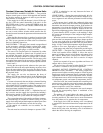
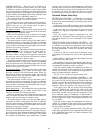
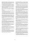
CHILLED WATER COIL COOLING CONTROL — The
cooling coil control adjusts the chilled water valve. The valve
is modulated to prevent space temperature from exceeding
the desired set point. The valve holds its normal position if
the space temperature is below the set point or the supply
fan is OFF.
If the fan is ON, the control reads the humidity sensor
(if supplied) and compares the value to the high humidity
limit.
If the humidity is higher than the high humidity limit, the
chilled water valve fully opens.
If the humidity is below the high humidity limit, the con-
trol reads the space temperature sensor and computes the supply-
air temperature required to satisfy conditions.
Once the required supply-air temperature has been cal-
culated, it is compared to the actual supply-air temperature
and the chilled water valve modulates to the position re-
quired to maintain desired conditions.
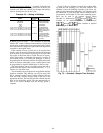
See Fig. 77 for cooling coil operation flow chart.
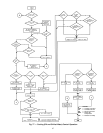
DIRECT EXPANSION COOLING CONTROL — The
direct expansion (DX) cooling control regulates the DX cool-
ing system. The DX cooling stages are energized and deen-
ergized to prevent the space temperature from exceeding the
desired set point. The stages remain off if the space tem-
perature is below the set point or the supply fan is OFF.
If the supply fan is ON, the control reads the humidity
sensor (if supplied) and compares the value to the high
humidity limit. If the humidity is higher than the high hu-
midity limit, the DX cooling stages are energized to main-
tain a minimum supply-air temperature. If the humidity is
below the limit, the control reads the space temperature sen-
sor and computes the supply-air temperature required to sat-
isfy conditions.
Once the required supply-air temperature has been cal-
culated, it is compared to the actual supply-air temperature
and the required DX cooling stages are energized to main-
tain the desired conditions.
See Fig. 77 for cooling operation and Fig. 78 for DX sub-
master gain operation. For more complete information, refer
to the Application Data book for Product Integrated Con-
trols with DX Cooling.
96