


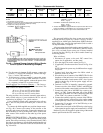
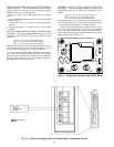
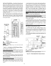

AIR QUALITY SENSOR — Air quality (AQ) sensors are
CO
2
sensors shipped inside the fan section for field instal-
lation. To wire the sensors after they are mounted in the con-
ditioned air space and return air duct, see Fig. 62 and the
instructions shipped with the sensors. For each sensor, use
two 2-conductor 20 AWG twisted-pair cables (unshielded)
to connect the separate 24 vac power source to the sensor
and the sensor to the option module (PSIO slave) terminals.
To connect each AQ sensor to the option module, identify
the positive (ϩ) and negative (−) terminals on the sensor;
connect AQ1 to terminals 25 and 26 and connect AQ2 to
terminals 28 and 29.
OUTSIDE AIR VELOCITY PRESSURE (OAVP) SEN-
SOR — The OAVP sensor is factory installed and wired. As
shown in Fig. 62, the sensor’s power wiring is connected to
TB2, 9 and 10 for 39L units or TB2, 29 and 30 for 39NX
units; the signal leads are connected to terminals 31 and 32
in the option module.
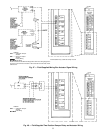
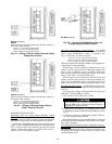
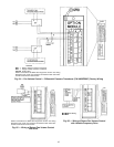
FAN VOLUME CONTROL (Fig. 63)
Airflow Monitoring Stations are field-selected and field-
installed in the supply and return air ducts; see Fig. 63.
Install each monitoring station in a straight portion of the
duct with any upstream or downstream elbows or fittings at
least 2.5 diameters away.
Use approved plenum tubing to connect each monitoring
station to the bulkhead fittings on top of the control box. For
runs up to 50 ft, use
1
⁄
4
-in. OD tubing. For runs over 50 ft,
use
3
⁄
8
-in. OD tubing.
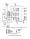
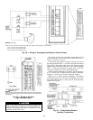
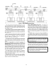
Differential Pressure Transducers for fan volume control are
factory-installed in the control box (two are supplied). The
power supply for the transducers is also factory installed.
Both transducers have pressure ranges of 0.0 to 1.0 in. wg
and produce 2 to 10 vdc signals. See Fig. 64 for wiring
details.
Note that if the velocity pressure of the supply and/or re-
turn air is below 0.75 in. wg, the system may require trans-
ducers with lower ranges than those of the default factory-
supplied transducers. As a general rule, size transducers
so that the maximum air velocity pressure is 75% of the
transducer’s maximum value. For example, if the 39L or
39NX unit produces a maximum air velocity pressure of
0.15 in. wg, a transducer with a maximum value of
0.20 in. wg can be used. Sizing the transducers according to
these guidelines ensures that they have good resolution.
Factory-Supplied Return Fans with Inlet Guide Vanes
(IGVs) are factory wired except for the air supply control
signal from the airflow monitoring stations, which is con-
nected in the field to the bulkhead fitting.
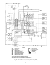
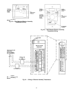
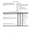
Return Fans with Field-Supplied IGV Actuators must be able
to receivea4to20mAsignal and may NOT have an im-
pedance of more than 600 ohms. An isolated power source
must be field-supplied and installed. See Table 9 for
recommended actuators.
To install actuators, see Fig. 65. Using a 2-conductor
20 AWG conductor cable (one twisted pair, unshielded) rated
for the application, connect the positive (ϩ) wire to terminal
37 in the option module. Connect the negative (−) wire to
terminal 38. Connect the 24 vac power leads to TB2,
terminals 23 and 24.
Field-Supplied Return Fans with Variable Frequency Drives
must have 4 to 20 mA signal input boards and their own
field-supplied and installed power sources.
To install return fans with variable frequency drives,
see Fig. 66. Using a 2-conductor 20 AWG conductor cable
(one twisted pair, unshielded) rated for the application, con-
nect the positive (ϩ) signal wire to terminal 37 in the
option module. Connect the negative signal (−) wire to
terminal 38.
The supply fan minimum set point must be equal to the
return fan minimum airflow, plus the delta airflow that is to
be maintained.
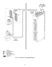
LEGEND
AQ — Air Quality Sensor
OAVP — Outside Air Velocity Pressure Sensor
Field Wiring
Factory Wiring
NOTE: See unit label diagram or Fig. 12 for remote-mount control
box connections.
Fig. 62 — Air Quality and OAVP Sensor Wiring
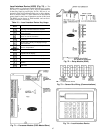
IGV — Inlet Guide Vane
Field Wiring
NOTE: Air monitoring stations are field supplied and installed; pres-
sure transducers are factory supplied and installed.
Fig. 63 — Field-Installed Fan Volume Control
62