


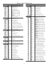
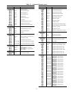
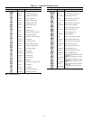
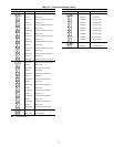
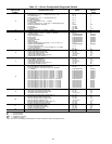
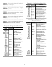

Table 16 — Service Configuration Ranges and Defaults
SERVICE
SUBFUNCTION
NUMBER
CONFIGURATION VALUE RANGE
FACTORY
DEFAULT
VALUE
3
Unit Type (0 = CV, 1 = VAV) 0/1 0
Cooling Type (0 = none, 1 = chilled water coil,2=DX) 0to2 1
DX Cooling Stages 0 to 8 2
Heating Type (0 = none, 1 = hot water/steam coil,
2 = electric heater)
0to2 1
Electric Heater Stages 0 to 8 0
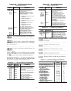
Mixed Air Dampers (0 = none, 1 = analog,
2 = 2-position)
0to2 1
Indoor-Air Quality Type (1 = single gas, 2 = differential/2 gases) 1/2 1
Mixed-Air Temperature Protection Yes/No Yes
Bus Number 0 to 239 0
Element Address 0 to 239 1
Password 0 to 9999 1111
4 English/Metric System (0 = English, 1 = Metric) 0/1 0
5
Nighttime Free Cooling Enabled/Disabled Disabled
Humidity Control (0 = none, 1 = analog, 2 = discrete) 0 to 2 0
Occupied Heating Enabled/Disabled Disabled
Space Temperature Reset Enabled/Disabled Disabled
Demand Limit Enabled/Disabled Disabled
Fan Tracking Enabled/Disabled Disabled
Constant Outside Air Enabled/Disabled Disabled
Night Purge Enabled/Disabled Disabled
Indoor Air Quality Enabled/Disabled Disabled
Indoor Air Quality Priority Level (high = 1, low = 2, none = 3) 1 to 3 2
Adaptive Optimal Start/Stop Enabled/Disabled Disabled
Timed Override Schedules 1 to 3 1
(1 = Time schedule no. 1, 2 = Time schedule no. 2, 3 = Both)
Timed Override Hours 0 to 4 0
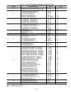
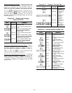
6
Heating Coil Master Proportional Gain 0 to 20.0 8.0
Heating Coil Master Integral Gain 0 to 2.0 0.3
Heating Coil Master Derivative Gain 0 to 20.0 0.0
Heating Coil Submaster Gain −20.0 to 20.0 −7.5
Heating Coil Submaster Center Value (%) 0 to 100 50
Heating Coil Fan ‘‘Off’’ Value (F) 35 to 65 40
7
Cooling Master Proportional Gain 0 to 20.0 8.0
Cooling Master Integral Gain 0 to 2.0 0.3
Cooling Master Derivative Gain 0 to 20.0 0.0
Cooling Coil Submaster Gain −20.0 to 20.0 −7.5
Cooling Coil Submaster Center Value (%) 0 to 100 80
Cooling High Humidity Limit (%) 0 to 99 99
8
DX Cooling Submaster Gain 2.0 to 25.0 *
DX Cooling Minimum Submaster Reference 0 to 60 40
DX Cooling Stage 1 Time Guardா Device (0 = disabled,
1 = enabled)
Enabled/Disabled Enabled
DX Cooling Stage 2 Time Guard (0 = disabled, 1 = enabled) Enabled/Disabled Enabled
DX Cooling Stage 3 Time Guard (0 = disabled, 1 = enabled) Enabled/Disabled Enabled
DX Cooling Stage 4 Time Guard (0 = disabled, 1 = enabled) Enabled/Disabled Enabled
DX Cooling Stage 5 Time Guard (0 = disabled, 1 = enabled) Enabled/Disabled Enabled
DX Cooling Stage 6 Time Guard (0 = disabled, 1 = enabled) Enabled/Disabled Enabled
DX Cooling Stage 7 Time Guard (0 = disabled, 1 = enabled) Enabled/Disabled Enabled
DX Cooling Stage 8 Time Guard (0 = disabled, 1 = enabled) Enabled/Disabled Enabled
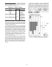
DX Cooling Stage 1 Logic Type (0 = normal, 1 = inverted) Normal/Inverted Normal
DX Cooling Stage 2 Logic Type (0 = normal, 1 = inverted) Normal/Inverted Normal
DX Cooling Stage 3 Logic Type (0 = normal, 1 = inverted) Normal/Inverted Normal
DX Cooling Stage 4 Logic Type (0 = normal, 1 = inverted) Normal/Inverted Normal
DX Cooling Stage 5 Logic Type (0 = normal, 1 = inverted) Normal/Inverted Normal
DX Cooling Stage 6 Logic Type (0 = normal, 1 = inverted) Normal/Inverted Normal
DX Cooling Stage 7 Logic Type (0 = normal, 1 = inverted) Normal/Inverted Normal
DX Cooling Stage 8 Logic Type (0 = normal, 1 = inverted) Normal/Inverted Normal
9
Inlet Guide Vanes Master Proportional Gain 0 to 5.0 0.5
Inlet Guide Vanes Master Integral Gain 0 to 2.0 0.3
Inlet Guide Vanes Master Derivative Gain 0 to 5.0 0.0
Inlet Guide Vanes Submaster Gain −10.0 to 10.0 5.0
Inlet Guide Vanes Submaster Center Value (%) 0 to 100 50
10
Mixed-Air Damper Master Proportional Gain 0 to 20.0 8.0
Mixed-Air Damper Master Integral Gain 0 to 2.0 0.3
Mixed-Air Damper Master Derivative Gain 0 to 20.0 0.0
Mixed-Air Damper Submaster Gain −20.0 to 20.0 −7.5
Mixed-Air Damper Submaster Center Value (%) 0 to 100 50
Mixed-Air Damper Minimum Position (%) 0 to 100 10
11
Electric Heat Master Proportional Gain 0 to 20.0 8.0
Electric Heat Master Integral Gain 0 to 2.0 0.3
Electric Heat Master Derivative Gain 0 to 20.0 0.0
Electric Heat Submaster Gain 0 to 15.0 5.0
12 NTFC Lock Out Temperature (F) 40 to 70 50
LEGEND
CV — Constant Volume
DX — Direct Expansion
NTFC — Nighttime Free Cooling
VAV — Variable Air Volume
*Value varies and is automatically calculated by the control. Override this feature by forcing the value.
82