


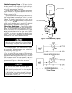
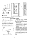
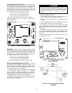
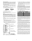

Supply-Air Temperature Sensor (Fig. 25) — The
supply-air temperature sensor (SAT) measures the tempera-
ture of the air as it leaves the supply fan. The sensor is factory-
installed on the fan scroll.
Return-Air Temperature Sensor (Fig. 25) — The
return-air temperature sensor (RAT) is shipped inside the fan
section. It measures the temperature in the return air duct.
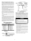
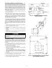
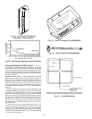
Mount the sensor in the middle of the return air duct ap-
proximately 4 to 5 ft from the return air damper. The sen-
sor’s probe tip must be within a straight length of duct.
Mount the sensor as follows:
1. Remove the cover of the sensor junction box.
2. Drill or punch a
5
⁄
16
-in. hole on the centerline of the re-
turn air duct as indicated in Fig. 26.
3. Drill or punch 2 holes through the sensor gasket into the
fan scroll.
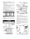
4. Remove the adhesive backing from the gasket; attach the
gasket to the outside of the junction box, aligning the holes
in the gasket with the holes in the box.
5. Attach the junction box to the duct with the 2 screws
provided.
6. Insert the probe assembly through the compression fit-
ting and into the duct. Tighten screws one half-turn past
finger tight. Do not overtighten.
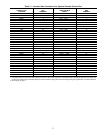
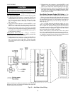
For distances up to 500 ft, use 2-conductor 20 AWG cable
to connect the sensor to the PIC control box terminals. Refer
to Field Wiring Connections section, page 32 for further de-
tails. See Table 3 for thermistor resistance vs. temperature
values.
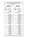
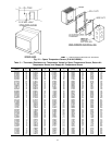
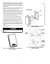
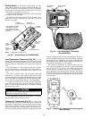
CONTROL SETTINGS
DIAL
SETTING
RELATIVE
HUMIDITY (%)
CONTROL
CURVE
20 50 80
A
78 F
(26 C)
73 F
(23 C)
68 F
(20 C)
A
B
73 F
(23 C)
68 F
(20 C)
63 F
(17 C)
B
C
68 F
(20 C)
63 F
(17 C)
59 F
(15 C)
C
D
62 F
(17 C)
58 F
(14 C)
53 F
(12 C)
D
Fig. 24 — Enthalpy Control Settings
Fig. 25 — Supply/Return Air Temperature Sensor
(P/N HH79NZ019)
Fig. 26 — Return-Air Temperature Sensor
Installation
44