


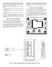
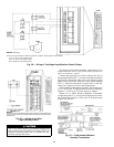
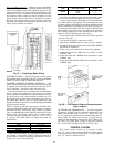

Pulse-Type Meter (Fig. 67) — Monitors power usage, which
is passed through the Carrier Comfort Network (CCN) for
use by the loadshed module of the Building Supervisor. The
meter must provide a dry contact signal (not exceeding 4 Hz
maximum). Using a 2-conductor 20 AWG shielded twisted-
pair conductor cable, connect one wire to terminal 35 of the
option module and the other wire to terminal 36. Connect
the drain wire to the ground lug inside the PIC control box
and remove the drain wire and shield on the meter end of the
cable. Tape to insulate, if required.
ELECTRIC HEATER — The electric heater is factory wired
and installed and is controlled by the PIC processor and DSIO.
There is no field wiring or installation required.
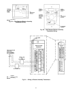
CARRIER COMFORT NETWORK INTERFACE — The
Carrier Comfort Network (CCN) communication bus wiring
is supplied and installed by the electrical contractor. It con-
sists of shielded, 3-conductor cable with drain wire.
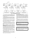
The system elements are connected to the communication
bus in a daisy-chain arrangement. The positive pin of each
system element communication connector must be wired to
the positive pins of the system element on either side of it;
the negative pins must be wired to the negative pins; the sig-
nal ground pins must be wired to signal ground pins. See
Fig. 68 for location of the CCN communication plug (COMM1)
on the processor module.
NOTE: Conductors and drain wire must be 20 AWG mini-
mum, stranded tinned copper. Individual conductors must be
insulated with PVC, PVC/nylon, vinyl, Teflon, or polyeth-
ylene. An aluminum/polyester 100% foil shield and an outer
jacket of PVC, PVC/nylon, chrome vinyl, or Teflon with a
minimum operating temperature range of −20 C to 60 C
is required. See Table below for cables that meet the
requirements.
MANUFACTURER CABLE NO.
Alpha 2413 or 5463
American A22503
Belden 8772
Columbia 02525
When connecting the CCN communication bus to a sys-
tem element, a color code system for the entire network is
recommended to simplify installation and checkout. The fol-
lowing color code is recommended:
SIGNAL
TYPE
CCN BUS CONDUCTOR
INSULATION COLOR
COMM1 PLUG
PIN NO.
ϩ RED 1
Ground WHITE 2
− BLACK 3
If a cable with a different color scheme is selected, a simi-
lar color code should be adopted for the entire network.
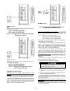
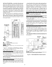
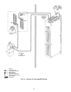
At each system element, the shields of its communication
bus cables must be tied together. If the communication bus
is entirely within one building, the resulting continuous shield
must be connected to ground at only one point. See Fig. 69.
If the communication bus cable exits from one building and
enters another, the shields must be connected to ground at
the lightning suppressor in each building where the cable
enters or exits the building (one point only).
To connect the 39L or 39NX unit to the network, proceed
as follows (Fig. 69):
1. Turn power to the PIC control box to OFF.
2. Remove the COMM1 plug from the processor module.
3. Cut the CCN wire and strip the ends of the RED, WHITE,
and BLACK conductors.
4. Using a wire nut, connect the 2 drain wires together.
5. Insert and secure the 2 RED wires to terminal 1 of the
COMM1 plug.
6. Insert and secure the 2 WHITE wires to terminal 2 of the
COMM1 plug.
7. Insert and secure the 2 BLACK wires to terminal 3 of the
COMM1 plug.
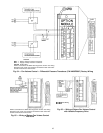
OUTDOOR-AIR THERMOSTAT — Use field-supplied,
2-conductor 20 AWG wire to connect the thermostat to the
DSIO and terminal block in the PIC control box. See
Fig. 70. Connect one wire between the thermostat and J3-1
on the DSIO. For 39NX units, connect a second wire be-
tween the other thermostat terminal and TB3-9 (TB2-10 for
39L units). For 39NX units, connect a third wire between
J3-2 on the DSIO and TB4-10 (TB2-9 on 39L units).
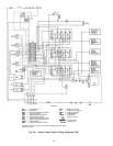
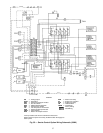
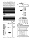
CONTROL SYSTEM
The control system consists of a processor module
(Fig. 71), sensors, and controlled devices. Available options
include a processor option module (Fig. 71), relay modules
(Fig. 72), and local interface device.
Field Wiring
Fig. 67 — Pulse-Type Meter Wiring
Fig. 68 — CCN Sensor Plug and Communication
Plug Locations
64