


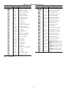
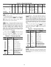
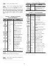

Table 15 — State of Items Controlled
MODE (DISPLAY
CODE)
RETURN
FAN
SUPPLY
FAN
OUTDOOR-
AIR
DAMPER
RETURN-
AIR
DAMPER
EXHAUST
DAMPER
SUPPLY FAN
INLET GUIDE
VANES (IGV)
RETURN
FAN IGV
HEAT
INTERLOCK
RELAY
ELECTRIC
HEAT ALL
STAGES
Pressurization (34) Off On Open Close Close Open to
Static Pressure
Set Point
Close On Off
Purge (36) On On Open Close Open Open to
Static Pressure
Set point
Open to
л ⌬ cfm
On Off
Evacuation (35) On Off Close Close Open Close Open Off Off
Fire Shutdown (37) Off Off Close Open Close Close Close Off Off
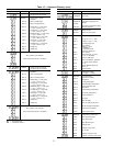
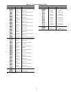
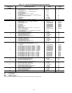
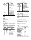
(Set point) — This subfunction displays the current
operating system set points.
To view set points, depress , then use the key
to display the occupied heat set point. Continue to depress
to display all the various system set points. Table 13
shows the order of the various set points.
------------------------------------------------
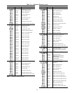
(Inputs) — The inputs subfunction displays the read-
ings at the various temperature sensors, fan status, static pres-
sure sensors, enthalpy switch, and freezestat. It also allows
the outside-air temperature sensor, enthalpy switch, return-
air relative humidity sensor, outside-air relative hu-
midity sensor, and filter status to be forced to a user deter-
mined value or status. The forced value overrides the value
that the control system actually reads. This permits opera-
tion in the event of a faulty sensor.
To read a sensor, enter , then scroll to the de-
sired sensor reading using the key. To force an input,
see Example 3. Table 13 shows the order of the readouts.
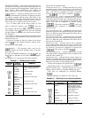
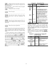
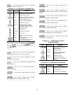
Example 3 — Forcing An Input Value
KEYBOARD
ENTRY
DISPLAY
RESPONSE
COMMENTS
INPUTS System inputs
Scroll past:
SPT X Space temperature
SAT X Supply air temperature
RT X Return air temperature
MAT X Mixed air temperature
OAT 60 Outside air temperature
8 0
OAT 80/FORCED
Outside air temperature value
forced to 80. NOTE: Forced
value toggles between value
and word forced
OAT 60
Outside air temperature
forced value removed.
Display no longer flashes
------------------------------------------------
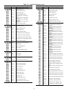
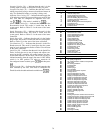
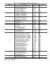
(Outputs) — The output subfunction displays or
forces the output value percentage of the inlet guide vanes,
mixed air damper and heating and cooling valves. It also
displays or forces the ON/OFF status of the supply fan and
heat interlock relay, displays the status of electric heat stages,
and displays optional output status for return fan volume con-
trol, analog output temperature control, discrete output tem-
perature control, discrete output time clock, and humidifier
stages.
To read a system output value, enter , then scroll
to the desired output using the key. To force a system
output value, see Example 4. Table 13 shows the order of
the output values.
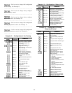
Example 4 — Forcing An Output Value
KEYBOARD
ENTRY
DISPLAY
RESPONSE
COMMENTS
OUTPUTS System Outputs
Scroll past:
IGV X Inlet guide vanes
MIXD X Mixed air damper
HCV X Heating coil valve
CCV X Cooling coil valve
SF OFF Supply fan off
SF ON/FORCED
Supply fan forced ON.
NOTE: Supply fan forced
value toggles between value
(SF ON) and word FORCED
SF OFF
Supply fan forced value re-
moved. Display no longer flashes
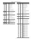
HISTORY FUNCTION
— Displays the 9 latest alarms generated by the
unit in the order of their occurrence. If 9 alarms are dis-
played, the occurrence of a 10th alarm shifts the first alarm
off the display.
------------------------------------------------
80