


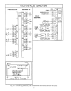
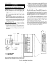
Variable-Frequency Drives — The input signal for
the inverter must be 4 to 20 mA. Use a 2-conductor
20 AWG (American Wire Gage) cable (single twisted pair,
unshielded) to connect the input of the inverter to the output
of the PIC control terminals. See Fig. 8.
Wire the inverter so that if it is placed in the manual or
bypass mode the low temperature thermostat and the high-
pressure switch (if supplied) are still in the motor control
circuit to protect the unit.
Adjust the minimum inverter speed to provide at least 10%
airflow when inlet guide vanes are at 0% (4 mA) and maxi-
mum design airflow when inlet guide vanes are at 100%
(20 mA). Use the local interface device to verify that the
supply fan status ( ) shows the fan is ON and that the
supply fan is operating at the lowest airflow adjustment. In-
crease inverter minimum speed as required. For additional
information, see the Quick Test section on page 103.
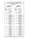
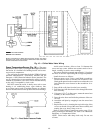
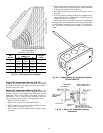
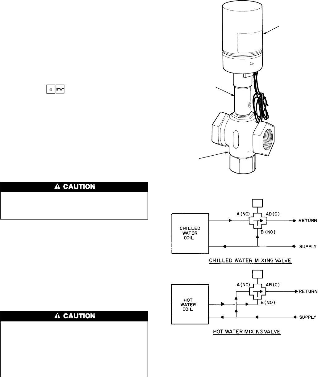
Water Valve Assemblies — Water valve assemblies
(Fig. 13) are shipped inside the fan section for field instal-
lation. All valve assemblies have electrically powered ac-
tuators. Each actuator has an external junction box for field
wiring. The junction box contains 24 vac power wires (WHITE/
BLUE, BLACK) and 4 to 20 mA signal wires (ϩRED,
−GREEN). The actuators operate the valve through a linear
stroke; if power is lost, a return spring reverses the stroke
and returns the valve stem to the normal position.
To prevent electric shock and equipment damage, dis-
connect the power to the control box before installing
valve assemblies. Turn power switch located on control
box door to OFF.
On installations where valve mounting space is limited,
use unions to couple valve assemblies to water lines. If unions
do not provide sufficient clearance, refer to the Valve
Troubleshooting section, page 109.
On chilled water applications or hot water applications with
1
1
⁄
2
to 3-in. valves, the valve actuators can be mounted in
any position above the centerline of the valve body. For steam
applications or hot water applications with
1
⁄
2
to 1
1
⁄
4
-in. valves
that have actuators and high-temperature linkage exten-
sions, mount the actuator above the centerline of the valve
body and 45 degrees from vertical. This position helps to
prevent actuator exposure to direct heat convection.
DO NOT install valve assembly where excessive mois-
ture, corrosive fumes, and/or vibration are present.
INSTALL all 2-way valve assemblies so that they close
against system flow. An arrow on the valve body indi-
cates the proper flow direction.
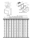
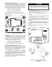
ALWAYS install 3-way mixing valve with 2 inlet flows
and one outlet. Normal flow will be from port B to port
AB with stem up. See Fig. 14.
ACTUATOR LINKAGE
VALVE BODY
VALVE ACTUATOR
Fig. 13 — Valve Assembly (Typical)
Fig. 14 — Three-Way Mixing Valve — Normal Flow,
Typical Piping
38