


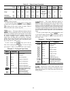
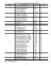
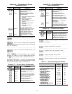
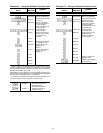

Example 16 — Configuration of Discrete
Temperature Control
KEYBOARD
ENTRY
DISPLAY
RESPONSE
COMMENTS
DO CTRL Discrete temperature control
configuration subfunction of
service function
SEN 1 Controlling temperature sensor
configured to sensor 1. Sensor
codes as follows:
1 - Supply-air temperature sensor
(standard)
2 - Outdoor-air temperature
sensor (standard)
3 - Mixed-air temperature sensor
(optional)
6 - Space temperature sensor
(standard)
7 - Return-air temperature
(standard)
34 - Other optional sensors
SEN 34 Controlling temperature sensor is
34, where sensor 34 is one of
2 optional sensor types
(space temperature sensor or
duct temperature sensor)
TYP 0
Discrete output control logic
(0 = normal logic, 1 = reverse
logic)
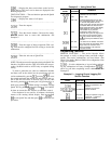
— Used to read service history. See Example 17.
------------------------------------------------
— Used to read or change field configuration
of service maintenance alarm duration and to read elapsed
time. See Example 18.
------------------------------------------------
— Used to read timed override history. See
Example 19.
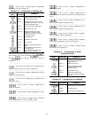
NOTE: The key is used to enable or turn on certain
functions; the CLR key is used to disable these functions.
The key may also be used to disable the functions.
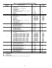
SET POINT FUNCTION — Set points are entered through
the keyboard. Set points can be changed within the upper
and lower limits, which are fixed. See Table 17.
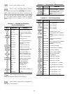
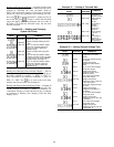
Example 17 — Service History Configuration
KEYBOARD
ENTRY
DISPLAY
RESPONSE
COMMENTS
SERVHIST
Service history configuration
subfunction of service function
SDAY 2
The unit had 2 starts within the
last 24 hours
ST 20
The unit had a total of 20 starts
since the unit was manufactured
FH 240
The fan has run for 240 hours
since unit manufacture.
4.06.30
The unit was last started on
Thursday at 6:30 am
4.19.00
The unit was last stopped on
Thursday at 7:00 pm
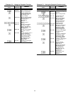
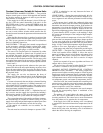
Example 18 — Service/Maintenance
Alarm Configuration
KEYBOARD
ENTRY
DISPLAY
RESPONSE
COMMENTS
SRV/MTN Service/Maintenance alarm
configuration subfunction of
service function
SMAL 2
Service/Maintenance alarm
limit is 2000 hrs (hours x 1000)
SMAL 5 Service/Maintenance alarm
limit is changed to 5000 hrs (This
represents the cumulative number
of hours the fan must be energized
before a service/maintenance alarm
is generated)
(NOTE: Entering a . disables the
alarm function)
SMEH 3 Service/Maintenance elapsed
hours is 3000 (This is the amount of
time elapsed from the start of the
service/maintenance alarm interval)
Example 19 — Timed Override History
KEYBOARD
ENTRY
DISPLAY
RESPONSE
COMMENTS
OVRDHIST
Timed override history
subfunction of service function
OHR 3 Within the current 24 hour period
(beginning at midnight), the unit
operated for 3 hours in the timed
override mode (mode 39)
— Displays system set points. See Table 13 for
sequence of set points.
------------------------------------------------
— Displays demand limit set points.
------------------------------------------------
— Displays time of day and day of week.
------------------------------------------------
— Displays Daylight Savings Time.
------------------------------------------------
— Displays holidays (month, day, and duration).
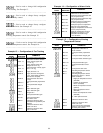
Table 17 — Set Point Ranges and Defaults
SET POINT
ALLOWABLE
RANGE
DEFAULT
Occupied Heating Set Point (F) 40 to 90 68
Occupied Cooling Set Point (F) 45 to 99 78
Unoccupied Heating Set Point (F) 40 to 90 55
Unoccupied Cooling Set Point (F) 70 to 99 90
Static Pressure
Set Point (in. wg)
0 to 5.0 1.5
Supply-Air Temperature
Set Point (F)
35 to 65 55
Delta CFM Set Point 0 to 250 0
Humidity Set Point (%) 0 to 100 40
Analog Temperature
Control Set Point (F)
40 to 100 40
Discrete Temperature
Control Set Point (F)
−40 to 245 0
Air Quality Sensor 1
Set Point (ppm)
0 to 2000 650
Air Quality Sensor 2
Set Point (ppm)
0 to 2000 650
Outside Air Velocity Pressure
Set Point (in. wg)
0.0 to 5.0 0.08
87