


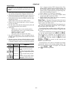
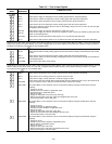
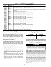

Table 18 — Test of Input Signals
KEYBOARD
ENTRY
DISPLAY
RESPONSE
COMMENTS/ACTION
INPUTS Field testing of inputs (X = current value. All temperatures should be Ϯ 2 degrees F from actual)
SAT X Verify that the supply-air temperature sensor reading agrees with the actual temperature.
OAT X Verify that the outdoor-air temperature sensor reading agrees with the actual temperature.
SPT X Verify that the space temperature sensor reading agrees with the actual temperature.
RAT X Verify that the return-air temperature sensor reading agrees with the actual temperature.
ENT X
Verify proper enthalpy reading. Move the knob on the enthalpy switch from A to D (or D to A) and verify that
the display readout changes.
SFS OFF Verify that the supply fan status is OFF when the supply fan is OFF.
SFS ON
Verify that the supply fan status is ON when the supply fan is ON. (Unit may be started by placing the HOA
switch in the HAND position.)
FRZ NRM Verify that the low limit thermostat reads Normal. If not, reset the low limit thermostat.
SP 0.0 Verify that the static pressure reads 0.0 in. wg with the fan OFF and HOA switch set at OFF (VAV units).
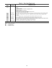
Listed below are steps which must be used to verify different options. If the unit is not equipped with MAT, RH, OARH, or FLTS, proceed with the
testing of the inputs to the Option Module. If the unit is equipped with any of these options, proceed with their respective testing as follows. If
an option is not present, press for the next available option.
RH XX
Verify that the relative humidity reading agrees with the actual relative humidity, checked with the local weather
bureau.
MAT X Verify that the mixed-air temperature sensor reading agrees with the actual temperature.
OARH XX
Verify that the outdoor-air relative humidity reading agrees with the actual relative humidity, checked with the
local weather bureau.
FLTS NRM Verify that the filter status reads Normal.
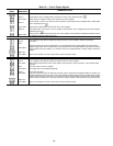
Listed below are steps which must be used to verify the inputs to the Option Module. If the unit is not equipped with the Option Module, proceed
with the testing of the outputs (Table 19). If the unit is equipped with the Option Module, proceed with the testing as follows. If an option
is not present, press for the next available option.
TEMP X Verify that the temperature sensor reading agrees with the actual temperature measured.
RVP X Verify that the return velocity pressure is 0 with the return fan OFF.
SVP X Verify that the supply velocity pressure is 0 with the supply fan OFF.
DHH NRM
Verify that the duct high humidity switch reads Normal when the adjustment knob is set to the maximum set
point or contacts are open. Verify that it reads ALM when contacts are shorted.
EVAC NRM At Terminal Block 3, short Terminals 5 and 8. Verify that the display changes to EVAC ALM. Verify the
following:
• Supply fan is OFF
• Outside and return dampers (if applicable) close
• Exhaust damper (if applicable) opens
• Return fan starts
• Supply fan inlet guide vanes close (VAV units only)
• Return fan inlet guide vanes open (VAV units equipped with return fans)
• Heat interlock Relay is OFF (VAV units)
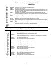
PRES NRM At Terminal Block 3, short Terminals 3 and 8. Verify that the display changes to PRES ALM. Verify the
following:
• Supply fan is ON
• Outside air damper (if applicable) opens
• Exhaust and return dampers (if applicable) close
• Return fan stops
• Supply fan inlet guide vanes open (VAV units)
• Return fan IGVs close (VAV units equipped with return fan)
• Heat Interlock Relay is ON (VAV units)
PURG NRM At Terminal Block 3, short Terminals 4 and 8. Verify that the display changes to PURG ALM. Verify the
following:
• Supply fan is ON
• Outside air and exhaust dampers (if applicable) open
• Return damper (if applicable) closes
• Return fan is ON
• Supply fan IGVs open (VAV units)
• Return fan IGVs open (VAV units equipped with return fan)
• Heat Interlock Relay is ON (VAV units)
104