


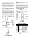

TO REASSEMBLE ACTUATOR TO VALVE BODY:
All 2-way normally-open valves:
1. Push the valve stem completely down and close seat valve.
NOTE: It may be necessary to shut down the system pump
to ensure valve stem is closed.
2. Loosen locknut and screw stem extension down fully on
valve stem to adjust stem extension for proper closure.
3. Attach actuator to valve linkage mounting bracket and
secure with self-tapping screws.
4. Make all necessary electrical connections.
5. Electrically power actuator by turning circuit breaker to
ON. Turn HOA switch to OFF position. Perform the heat-
ing coil valve quick test to stroke the actuator to its full
extended position. See Example 26. Leave the unit in test
mode and proceed to Step 6.
6. Screw the stem extension up until its hole aligns with the
hole in the actuator piston.
7. Screw the stem extension 2 full turns farther up into the
actuator piston.
8. While still in Quick Test, press to retract actuator
piston and align holes to insert connecting pin. Exit
Quick Test.
9. Tighten the locknut against the stem extension.
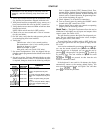
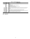
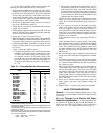
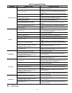
Example 26 — Heating Coil Valve Test
(2-Way Normally Open)
KEYBOARD
ENTRY
DISPLAY
RESPONSE
COMMENTS
OUTPUTS Entering factory test of outputs
HCV % Entering heating coil valve test
HCV TEST
The hot water/steam valve strokes
to 100%
EXIT TST Exit Quick Test
TST CMPL Test completed
NOTE: For more complete instructions on the Quick Test procedure,
see Quick Test in the Start-Up section, pages 103-108.
All 2-way normally-closed and 3-way mixing valves:
1. Raise the valve stem completely up and close valve seat.
NOTE: It may be necessary to shut down the system pump
to ensure valve stem is closed.
2. Loosen locknut and screw stem extension down fully on
valve stem to adjust stem extension for proper closure.
3. Attach actuator to valve linkage mounting bracket and
secure with self tapping screws. The actuator should be
fully retracted with no power or signal present.
4. Screw the stem extension up until its hole aligns with the
hole in the actuator piston.
5. Screw the stem extension down 2 full turns away from
the actuator piston.
6. Turn circuit breaker to ON. Electrically connect the ac-
tuator. Using the cooling coil valve quick test, extend the
actuator piston to align holes and insert the connecting
pin. See Example 27. After inserting connecting pin, exit
Quick Test.
7. Tighten the locknut against the stem extension to secure
to stem.
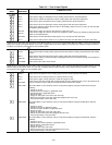
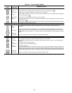
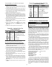
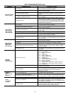
Example 27 — Cooling Coil Valve Quick Test
(2-Way Normally Closed)
KEYBOARD
ENTRY
DISPLAY
RESPONSE
COMMENTS
OUTPUTS Entering factory test of outputs
HCV %
Scroll past heating coil valve test
by pressing key
CCV % Cooling coil valve test
CCV TEST
Cooling coil valve actuator piston
extends (Insert connecting pin)
EXIT TEST Exit factory test
TST CMPL Test completed
NOTE: For more complete instructions concerning the Quick Test pro-
cedure, see Quick Test in the Start-Up section, pages 103-108.
CONTROL MODULE TROUBLESHOOTING
To prevent electrical shock and equipment damage, turn
off all power to the PIC control box before removing or
replacing modules.
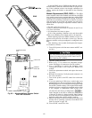
General — The processor module (PSIO master), option
module (PSIO slave) and relay module (DSIO) all perform
continuous diagnostic evaluations of the condition of the hard-
ware. Proper operation of these modules is indicated by LEDs
(light-emitting diodes). The PSIO LEDs are located on the
top of the module, and the DSIO LEDs are on the front of
the module. See Fig. 83.
RED STATUS LED — If the LED is blinking continuously
at a one-second rate, the module is operating normally. If the
LED is lighted continuously, there is a problem that may re-
quire replacement of the module.
If the red LED is off continuously, check the power sup-
ply to the module. If there is no input power, check the fuses.
If a fuse is blown, check for shorted wiring or for a non-
functional module. If the fuses are not blown, check for a
bad transformer or open secondary of the transformer.
GREEN COMMUNICATIONS LEDs — On a PSIO mod-
ule, the green LED closest to the COMM connectors indi-
cates the status of communications between modules. When
used, the other green LED on the module indicates the status
of external CCN communications.
The green LED that indicates module communications should
blink continuously whenever the power is on. If the green
LED is not blinking, check the red LED. If the red LED is
normal, check the module address switches as shown in
Fig. 82. The correct addresses follow:
Processor Module (PSIO Master) — 01 (factory default)
Option Module (PSIO Slave) — 31
High-Voltage Relay Module — 19
(DSIO for Electric Heat
or
DX Control)
High-Voltage Relay Module — 49
(DSIOs for Electric Heat
and
DX Control)
If all of the preceding modules except the processor mod-
ule indicate communication failure, check the COMM plug
on the processor (PSIO master) module for proper seating
and check the communications bus wiring as shown in
Fig. 69 on page 65. If the condition persists even though
plug connections and wiring are correct, replace the proces-
sor module as described in the Module Replacement
section.
111