


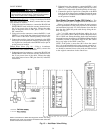
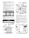

NOTE: This sensor uses a resistance temperature device (RTD)
element. Polarity is not a consideration.
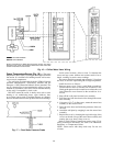
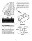
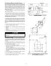
When space does not allow working inside the duct, mount
as follows (Fig. 22):
1. Open a duct penetration on the opposite side of the sen-
sor junction box.
2. Wrap the element around a
3
⁄
4
-in. PVC pipe, cut holes
near the center of the duct on both sides and feed the pipe
with sensor element through the hole.
3. Secure the seal around the PVC pipe.
NOTE: If local codes do not permit the use of PVC, use
EMT instead.
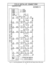
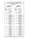
Refer to Field Wiring Connections section, page 52 for
wiring instructions and details. See Table 5 for RTD resis-
tance vs temperature values.
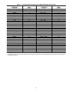
Table 5 — RTD Resistance vs Temperature Values
for Mixed-Air Temperature Sensor
RESISTANCE
(Ohms)
TEMP
(F)
RESISTANCE
(Ohms)
TEMP
(F)
RESISTANCE
(Ohms)
TEMP
(F)
693 −40 940 50 1223 140
719 −30 970 60 1257 150
745 −20 1000 70 1290 160
772 −10 1031 80 1325 170
799 0 1062 90 1360 180
827 10 1093 100 1395 190
854 20 1125 110 1430 200
883 30 1157 120 — —
912 40 1190 130 — —
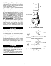
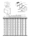
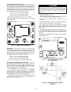
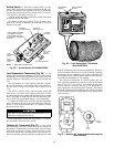
Enthalpy Switch (Fig. 23) — The enthalpy switch and
mounting template are located in a box shipped inside the
fan section.
The enthalpy switch is normally mounted in a horizontal
position with the sensing element exposed to freely circu-
lating outdoor air.
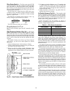
DO NOT install enthalpy switch in locations where ex-
cessive moisture, corrosive fumes, and/or vibration are
present.
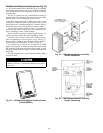
Mount the switch as follows:
1. Position mounting template on duct. Remove adhesive
backing and press template onto outside air duct.
2. Drill four
1
⁄
8
-in. mounting holes as indicated on the
template.
3. Cut out center portion of duct as outlined on template.
4. Mount controller to duct using screws provided.
If no outside air duct is present, mount the enthalpy switch
on a field-supplied and installed plate upstream of the out-
side air damper.
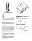
Connect the red and blue wires of the enthalpy switch to
the PIC control box terminals. Refer to Field Wiring
Connections section, page 52 for further details.
CONTROL RANGES — See Fig. 24 for control settings and
intermediate settings.
Fig. 21 — Mixed-Air Temperature Sensor
(P/N HH79NZ021) Installation
Fig. 22 — Alternate Mixed-Air Temperature
Sensor Installation
A
B
C
D
Y
E
L
R
E
D
B
L
U
MOUNTING HOLES
Fig. 23 — Enthalpy Switch (P/N HH57AC076)
43