


For factory-supplied actuators that are field-installed, the
24 vac power source is included with the unit wired in the
control box. For field-supplied actuators, a 24 vac power source
must be field-supplied and installed for each actuator.
To prevent equipment damage: Power must NOT be con-
nected to an earth ground; actuator case must NOT be
connected to control input terminals.
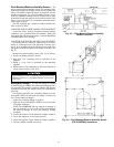
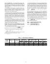
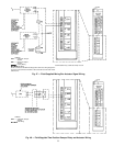
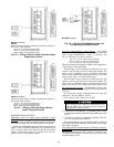
Field-Supplied Exhaust Damper — Wire the 4 to 20 mA sig-
nal of the factory-supplied exhaust damper actuator as fol-
lows (Fig. 46):
1. Select a 20 AWG twisted pair conductor cable rated for
the application. Identify the positive (ϩ) and negative (−)
signal contacts on the actuator.
2. Install cable from the actuator to the PIC control box.
3. Remove jumper no. 84 from between terminals TB2, 7
and 8. Connect positive (ϩ) lead to terminal 8 of TB2.
Connect negative (−) lead to terminal 7 of TB2.
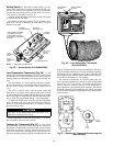
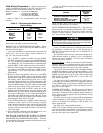
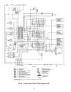
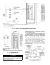
Field-Supplied Modulating Mixing Box — Wire the 4 to
20 mA signal of the factory-supplied damper actuator as fol-
lows (Fig. 47):
1. Select a 20 AWG twisted pair conductor cable rated
for the application. Identify the positive (ϩ) and
negative (−) signal contacts on the actuator.
2. Install cable from the actuator to the PIC control box.
3a. For the outside-air damper (OAD) actuator, connect the
positive (ϩ) lead to pin 40 of the processor module. Con-
nect the negative (−) lead to terminal 6 of terminal block
2 (TB2).
b. If the actuator is factory-supplied, connect the actua-
tor’s 24 vac power wires to TB2, terminals 19 and 20.
If the actuator is field-supplied, connect the power wires
to a separate, isolated 24 vac power source.
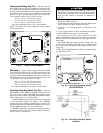
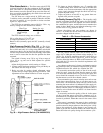
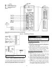
LEGEND
ENT — Enthalpy Switch
MAT — Mixed-Air Temperature Sensor
OAT — Outside-Air Temperature Sensor
RAT — Return-Air Temperature Sensor
SPT — Space Temperature Sensor
Field Wiring
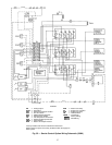
NOTE: Connections for 39NX with integral PIC shown. See wiring diagrams in
Fig. 9 and 12 for terminal connections in 39L control box and all remote-mount
control boxes.
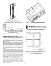
Fig. 44 — Field Wiring of Sensors
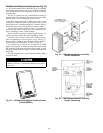
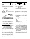
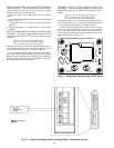
IMPORTANT: Jumper may be connected from E1 to E3. Move jumper to
connect E2 and E3 before installing sensor, otherwise incorrect space tem-
perature values are generated.
Fig. 45 — Space Temperature Sensor Wiring
53